8. FITTING THE MIXER VALVE
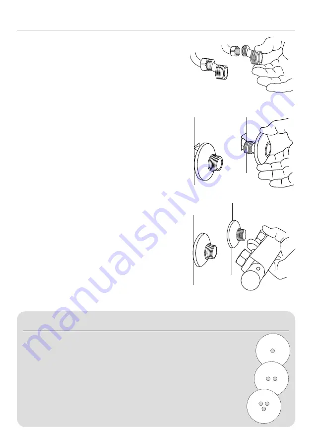
1. The supply pipework can be plumbed from above or
below but must finish at the suitable connections,
which should be at 150mm centers. An Easy Fit
Kit can be purchased to make installation easier
if required. Connect the 15mm pipework using
standard compression fittings (Fig 1).
It is recommended you leave enough adjustment
in the feed pipes to allow leveling and positioning of
the valve.
2. Screw the supplied domed cover onto the dogleg
fittings until tight to the wall. If required put a bead
of silicone sealant around the inside of the domed
cover to prevent moisture entering the wall. The
domed cover can be adjusted depending on the
length of exposed thread from the elbow (Fig 2).
NOTE: The valve will not work correctly if the feeds are
connected the wrong way round.
3. Offer the mixer valve to the fittings, making sure
the sealing washers are in place, screw the unions
onto the fittings. The mixer valve must be positioned
horizontally with the hot supply on the left hand side
of the outlet (Fig 3).
9. PRESSURE BALANCING (IF SUPPLIED)
The thermostatic mixer valve is designed to work best when the feed pressures of both hot
and cold water are the same. If there is a difference in pressure it will cause the flow of water
through the valve to pulse rather than being a steady flow. This pulsing can be reduced by
putting one of the metal disks with holes into the higher pressure feed to the valve. This
restricts the flow and reduces the pulsing.
To maximise the volume of water through the valve the disk with the most holes should be
tried first. If this does not work the others should be tried until a satisfactory result
is obtained.
If the water pressures to hot and cold are the same these disks do not need to be used.
Spillover
level
1
2
3


