FWMurphy - AS705S, AS710S, AS720S and AS730S PC communication and software mi5266 revision D 19
th
June 2002 p2/8
2.2 Hardware Connection
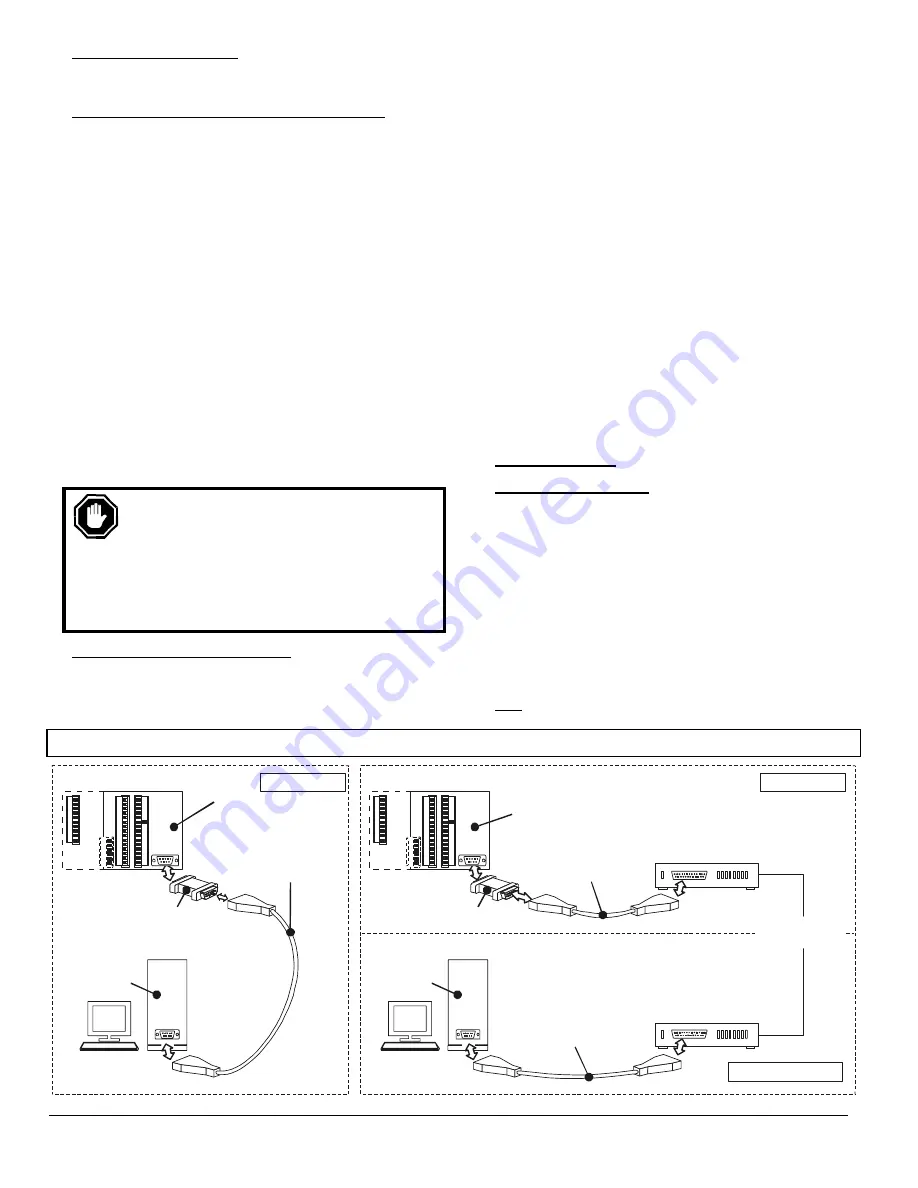
Typical connections for local and remote (modem) systems are
shown at the foot of the page.
2.2.1 Local communication (distances up to 10 metres)
Over short distances, the Autostart may be simply connected to a
PC or laptop using interface unit AS7CC and serial lead AS7CA
or AS7CB (see diagram below left). To connect up the system:-
1. Ensure that both Autostart and PC/laptop are powered down.
2. Take interface unit AS7CC, and plug the end marked
‘Autostart’ (or 'AS7xx') into the 9-way D-connector socket
at the Autostart's rear. Tighten the two securing screws.
3. Plug the (9-way end) of the serial lead into the interface, at
the end marked ‘PC’. Connect the other (9 way or 25 way)
end of the lead into a spare serial (COM) port on the
PC/laptop.
4. The Autostart may be wired into the control panel as for
normal operation. Alternatively, make the following
minimum electrical connections:-
•
Positive DC supply to pins 3, 4 and 11
•
Negative DC supply to pins 1 and 28.
5. For laptop computers, ensure that the mains AC supply is
disconnected (see caution below). Switch on the PC or
laptop, power up the Autostart into Auto mode, and run the
software (see section 3.2).
WARNING:
For Autostart communications, laptop
computers MUST be used in stand-alone ‘battery’
mode only, with the AC power supply
disconnected. Failure to disconnect the AC supply
may result in damage to both laptop and Autostart.
The damaging electrical currents can be caused by
voltage differences between the Autostart and laptop,
where the laptop AC power supply is ungrounded.
2.2.2 Remote (Modem) Communication
Two modems are required, one connected to the Autostart (at
the generator site) and one connected to the PC (at the
remote ‘control’ site).
The modems must be RS232 and Hayes AT compatible, and
will also usually need to comply with the technical and legal
requirements of the connected telephone network. The
Autostart/ generator site modem should ideally use an
uninterruptable power supply (usually a battery/DC system).
Connection at the generator site:-
1. Ensure that both modem and Autostart are powered down.
2. Take the interface unit AS7CD, and plug the end marked
‘Autostart’ or ‘AS7XX’ into the 9-way D-connector socket
at the Autostart rear. Tighten the 2 securing screws.
3. Connect the modem lead between interface and modem.
4. Connect up the modem’s telephone and power supply
leads, as specified by the modem manufacturer.
5. Power up the system: modem first, then Autostart.
At the PC control site, connect the modem to the PC, telephone
network and power supply in accordance with the manufacturer’s
instructions. (This may not be necessary if the PC is already
fitted with an internal modem card. Note, however, that the PC
software will only operate with modems configured on serial ports
COM1 or COM2: the software does not support internal modems
configured with COM3 or COM4 port settings.)
3 PC
SOFTWARE
3.1 Software Installation
Before any communication can occur between Autostart and PC,
software model AS7CK must be installed on the PC and correctly
configured. All the instructions following relate to version 1.07 of
this software, released January 2001.
Software AS7CK is designed to run on an IBM compatible
PC running Microsoft Windows® 3.1, 3.11, ’95 or '98. The
software is a DOS based program supplied on one 3.5",
1.44Mb floppy disk, or available (free of charge) from the
‘downloads’ section of our website:
www.fwmurphy.co.uk
..
The software can be used with modem/serial port settings of
COM1 or COM2: note that COM3 or COM4 port settings are
not
supported.
Autostart to PC Connection
Autostart
705, 710, 720 or 730
Autostart
710, 720 or 730
Generator Site
Generator Site
Remote Contol Site
Modem Communications
Local Communications
Software
AS7CK
Software
AS7CK
Interface
AS7CC or AS7CD
Modem interface
AS7CD
Interface to PC lead
AS7CA (9 way F - 9 way F) or
AS7CB (9 way F - 25 way F)
RS232 Hayes AT compatible
modem, DC powered
(not supplied by Murphy)
RS232 Hayes AT
compatible modem
(not supplied by Murphy)
Public Switched
Telephone Network
PC
PC
COM
COM
Interface (9 way)
to modem lead
(not supplied by Murphy)
PC - modem lead
(not supplied by Murphy)
70
71
72
73
74
75
76
77
78
79
70
71
72
73
74
75
76
77
78
79
1
2
3
4
5
6
7
8
9
10
11
12
13
14
15
1
2
3
4
5
6
7
8
9
10
11
12
13
14
15
16
17
18
19
20
22
23
24
25
26
27
28
29
30
16
17
18
19
20
22
23
24
25
26
27
28
29
30
21
21
50
51
52
53
54
55
50
51
52
53
54
55


