Temperature
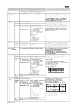
Compensating Type
High Dielectric
Constant Type
1 Operating
△
C,1X
:-
55
℃
to 125
℃
B1,B3,F1
:-
25
℃
to 85
℃
Standard Temperature
:
20
℃
Temperature Range
0C
:-
55
℃
to 150
℃
R1,R7,C7
:-
55
℃
to 125
℃
(R6,R7,R9,C7,C8,F5,L8
:
25
℃)
Other
:-
25
℃
to 85
℃
R6
:-
55
℃
to 85
℃
R9,L8
:-
55
℃
to 150
℃
C8
:-
55
℃
to 105
℃
F5
:-
30
℃
to 85
℃
2 Rated Voltage
See the previous pages.
The rated voltage is defined as the maximum voltage which may be
applied continuously to the capacitor.
When AC voltage is superimposed on DC voltage, V
P-P
or V
O-P
,
whichever is larger, should be maintained within the rated voltage range.
3 Appearance
No defects or abnormalities.
Visual inspection.
4 Dimension
Within the specified dimensions.
Using calipers. (GRM02 size is based on Microscope)
5 Dielectric Strength
No defects or abnormalities.
No failure should be observed when 300% of the rated voltage
(temperature compensating type) or 250% of the rated voltage
(high dielectric constant type) is applied between the
terminations for 1 to 5 seconds, provided the charge/discharge
current is less than 50mA.
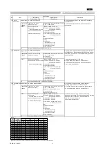
6 Insulation
C
≦
0.047
μ F:More than 10000MΩ
The insulation resistance should be measured with a DC voltage
Resistance
C
>
0.047
μ F:More than 500Ω·F
not exceeding the rated voltage at 20
℃
/25
℃
and 75%RH max.
C:Nominal Capacitance
and within 2 minutes of charging, provided the charge/discharge
current is less than 50mA.
7
Capacitance
Within the specified tolerance.
The capacitance/D.F. should be measured at 20
℃
/25
℃
at the
frequency and voltage shown in the table.
8 Q/Dissipation
30pF and over:Q
≧
1000
[
B1,B3,R1,R6,R7,C7,C8,L8
]
Factor (D.F.)
30pF and below:Q
≧
400+20C W.V.:100V :0.025max.(C
<
0.068
m
F) (1)Temperature Compensating Type
:0.05max.(C
≧
0.068
m
F)
C:Nominal Capacitance(pF) W.V.:50V/25V :0.025max.
W.V.:16V/10V :0.035max.
W.V.:6.3V/4V :0.05max.(C
<
3.3
m
F)
:0.1max.(C
≧
3.3
m
F)
[R9]
(2)High Dielectric Constant Type
W.V.:50V: 0.05max.
[F1,F5]
W.V.:25Vmin
:0.05max. (C
<
0.1
m
F)
:0.09max.(C
≧
0.1
m
F)
W.V.:16V/10V:0.125max.
W.V.:6.3V:0.15max.
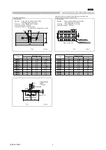
9
Capacitance
No bias
Within the specified
B1,B3 : Within ±10%
The capacitance change should be measured after 5min. at each
Temperature
tolerance.(Table A)
(-25°C to +85°C)
specified temp.stage.
Characteristics
R1,R7 : Within ±15%
(1)Temperature Compensating Type
(-55°C to +125°C)
The temperature coefficient is determind using the capacitance
R6 : Within ±15%
measured in step 3 as a reference.
(-55°C to +85°C)
When cycling the temperature sequentially from step 1 through
R9 : Within ±15%
5 (
Δ C
:
+20
℃
to +125
℃:
other temp.coeffs.:+20
℃
to +85
℃
) the
(-55°C to +150°C)
capacitance should be within the specified tolerance for the
C7 : Within ±22%
temperature coefficient and capacitance change as Table A-1.
(-55°C to +125°C)
The capacitance drift is caluculated by dividing the differences
C8 : Within ±22%
between the maximum and minimum measured values in the
(-55°C to +105°C)
step 1,3 and 5 by the cap.value in step 3.
F1 : 30/-80%
(-25°C to +85°C)
F5 :22/-82%
(-30°C to +85°C)
L8 : Within ±15%
(-55°C to +125°C)
: 15/-40%
(+125°C to +150°C)
50% of
B1: 10/-30%
the rated
R1: 15/-40%
voltage
F1: 30/-95%
2) High Dielectric Constant Type
The ranges of capacitance change compared with the 20
℃
value over the temperature ranges shown in the table should be
Capacitance
Within±0.2% or±0.05pF
within the specified ranges.*
Drift
(Whichever is larger.)
In case of applying voltage, the capacitance change should be
*Not apply to 1X/25V
measured after 1 more min. with applying voltage in
equilibration of each temp. stage.
*Initial measurement for high
dielectric constant type
Perform a heat treatment at 150
+0/-10
℃
for one hour and then
set for 24±2 hours at room
temperature.
Perform the initial measure-ment.
■
SPECIFICATIONS AND TEST METHODS
No
Item
Specification
Test Method
Step
Temperature(
C)
1
20
±
2
2
-55
±
3(for
C)/-25
±
3(for other TC)
3
20
±
2
4
125
±
3(for 2C/3C/4C)
150
±
3(for 0C)
85
±
3(for other TC)
5
20
±
2
Step
Temperature(℃)
Applying
voltage
1
20±2/25±2
No bias
2
-55±3(for R1,R7,R6,R9,C7,C8,L8)/
-25±3(for B1,B3,F1)/
-30±3(for F5)
3
20±2/25±2
4
125±3(for R1,R7,C7)/150±3(for R9,L8)
105±3(for C8)/85±3(for B1,B3,R6,F1,F5)
5
20±2
50% of the
rated voltage
6
-55±3(for R1)/-25±3(for B1,F1)
7
20±2
8
125±3(for R1)/85±3(for B1,F1)
Capacitance
Frequency
Voltage
C
≦
1000pF
1±0.1MHz
0.5 to 5Vrms
C
>
1000pF
1±0.1kHz
1±0.2Vrms
Capacitance
Frequency
Voltage
C
≦
10μF
1±0.1kHz
1±0.2Vrms
C
>
10μF
120±24Hz
0.5±0.1Vrms
JEMCGS-0001S
2

