


GETTING STARTED
18
Dragonfly
™
Nano MTQN-MNG3-B02 Device Guide
Chapter 6 – Getting Started
Communicating with the Device
Following are three options for communicating with the device.
1.
Install USB drivers and plug into the micro USB connector. No need for a host board.
2.
Access the device's USB interface via pins 6, 7, and 24 of the 40-pin connector. Data pins 6 and 7 are
parallel with the micro USB connector on the MTQN. There is no connection to pins 6, 7 and 24 on
the MTUDK-ST-Cell. VUSB_SELECT is isolated from VUSB of the micro USB connector.
3.
Establish serial communication using Multitech developer board MTUDK2-ST-Cell. See the
Universal
Developer Kit 2.0 Developer Guide
(PN S000610) for more information.
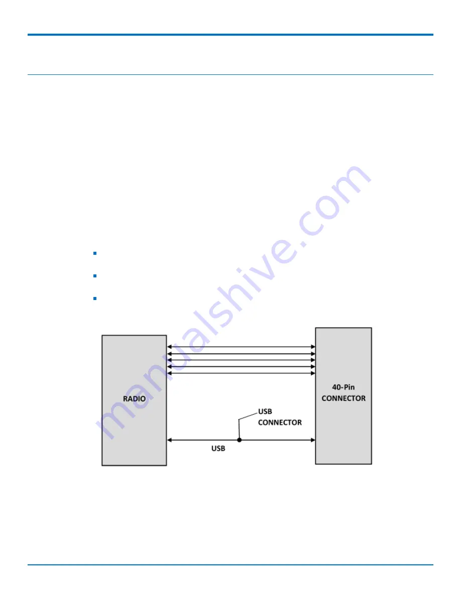
Communications Flow
The MTQN-MNG3-B02 provides a full UART interface from the cellular radio to the user application. Model B02
also provides a USB interface.
Note:
When the USB interface is used via the 40-pin connector (VUSB_SELECT is 5V) or the USB
connector, the serial interface to the radio will not function.
Pin 24 VUSB_SELECT must be pulled to 5V to enable the USB interface available through the 40-
pin connector.
Switching between the USB interface and serial port requires a reset. The cellular radio checks
for a USB connection upon reset. If USB is not present, it will only use the serial port. If USB is
present upon reset, it will only use USB.
Installing a SIM Card
Note:
When using the Dragonfly™ Nano with a developer board, install the SIM card before mounting the
Dragonfly™ Nano on the developer board.
Note:
All Dragonfly™ Nano models require the use of a Micro SIM (3FF) card.
To install the SIM card:
Содержание Dragonfly Nano MTQN-MNG3-B02
Страница 1: ...Dragonfly Nano MTQN MNG3 B02 Device Guide ...


