Recommended Installation Procedure
Doc. No 10-8381
Release 1.0, 1/14/2005
Page 4 of 4
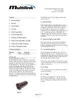
6.0 Closure Preparation
Refer to Figure 7
The closure must be disassembled for installing the
feeder/express cables into the multicentric grommets.
6.01
Back off the two spring loaded bolts securing
t
he
“
V”
ba
nd
a
nd
r
e
move
.
6.02
Sl
i
de
t
he
Dome
a
nd
“
O”
r
i
ng
of
f
a
nd
pr
ot
e
c
t
t
he
“
O”
r
i
ng
f
r
om
c
ont
a
mi
na
t
i
on
6.03
Remove the two Phillip Head screws securing
the Slack Storage Basket and set all aside.
6.04
Ba
c
k
of
f
t
he
t
hr
e
e
he
x
he
a
d
bol
t
s
us
i
ng
a
7/
16”
Nut Driver securing the End plate sections and
expose the two multicentric grommets.
6.05
Remove the two Multicentric grommets.
Figure 7
7.0 Sheath and CSM Retention
The following information provides installation
information regarding the different types of cable
sheath and bundling designs. Note that the CSM
clamp provides both cable strain relief and CSM
termination. If Core Tube cabling is being installed
the CSM extension of the combination clamp will be
removed.
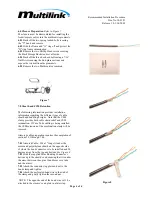
Armored cable preparation requires the completion of
sections 7.01 through 7.04.
7.01
Ar
mor
ed
Ca
bl
e
;
Sl
i
t
a
1”
l
ong
s
l
i
t
unde
r
t
he
armor and polyethylene sheath on the opposite side
of where the bond connector is to be installed and 90
degrees away from the top and bottom.
See Figure 8
7.02
Sl
i
de
t
he
s
uppl
i
e
d
Mi
ni
Bondi
ng
Conne
c
t
or
’
s
bot
t
om
up
t
o
t
he
s
he
a
t
h’
s
e
nd
e
ns
ur
i
ng
t
ha
t
i
t
i
s
unde
r
the armor between the optical bundles or core tube
and the armor.
7.03
Attach the connector top plate and nut to the
bond clamp and tighten
7.04
Attach the perforated bond wire to the stud of
the clamp and gently tighten the second nut.
NOTE: The opposite end of the bond wire will be
a
t
t
a
c
he
d
t
o
t
he
c
l
os
ur
e
’
s
e
nd
pl
a
t
e
i
n
a
l
a
t
e
r
s
t
e
p.
Figure 8


