


10
HG-2 LOW-PROFILE DIRECT DISCHARGE UNIT
HG-2 DISASSEMBLY AND REASSEMBLY INSTRUCTIONS
to bleed residual pressure within
the line.
4.
If you have dechlorination,
remove from piping by loosening the
nut and disconnect, 'Skip to #5, if
no dechlorination.
5.
Loosen the union and remove
piping and control valve.
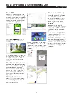
Electrical System Check
1.
Unscrew Solenoid from control
valve.
2.
Make sure controller is attached
to solenoid via connectors (remove
adaptor if present).
3.
Position thumb or other object in
front of plunger, leaving a slight gap
(
1/8
"), to prevent plunger and spring
from ejecting away from work space.
4.
Run manual flush for 2 minutes.
NOTE: Plunger inside solenoid
should be down when running and
up when off.
5.
If everything checks out, reinstall
solenoid in valve.
6.
Avoid cross threading. Any
resistance means solenoid is
not going in correctly and cross
threading may occur. Do not
overtighten. Tighten until snug.
If everything checks out, the
electrical system is in working order.
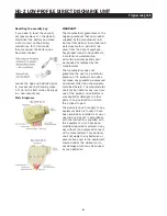
Disassembly and Check
For units manufactured from August
2004 to present, use the following
directions. If you have an older
model with a different valve and lost
the manual, please call us at 877-
864-8500 to get the manual for
that model.
1.
Remove six (6) bolts from top
cover.
2.
Slowly pull cover off the valve.
3.
Remove rubber diaphragm and
inspect for holes or worn areas.
4.
Inspect valve screen plug to be
certain it is not damaged and clear
of debris.
Although the Hydro-Guard® HG-2
Direct Discharge with RPZ, Double
Check or Air Gap was delivered
completely assembled, it may be
necessary and/or desirable to
disassemble portions of the Unit,
or the Unit in its entirety, In order
to allow for required service and
maintenance. If disassembly
is necessary, please follow the
directions below. Always close the
curb stop before working on the
unit.
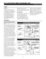
HG-2 Removal of Internal
Components (FOR RPZ AND
DOUBLE CHECK MODELS)
1.
Shut off water supply and secure
isolation valve.
2.
Remove the housing cover by
tilting the housing upward while
lilting slightly on its end. Once
the retaining pin, located in the
opposite end of the housing, is
clear of the cover, lilt upward to
remove the cover.
3.
Use the sample port connection
to bleed off residual pressure within
the line.
4.
Disconnect the quick connectors
on the solenoid. Remove all
upgrades from piping.
5.
Loosen the unions on each side
of the control valve and RPZ or
Double Check Valve.
6.
Remove nut from support
bracket.
7.
Remove all piping from housing.
HG-2 Removal of Internal Compo-
nents (FOR AIR GAP MODEL)
1.
Shut off water supply and secure
isolation valve.
2.
Remove the housing cover by
tilting the housing upward while
lilting slightly on its end. Once
the retaining pin, located in the
opposite end of the housing, is
clear of the cover, lift upward to
remove the cover.
3.
Use the sample port connection
5.
Remove valve screen plug and
inspect valve screen for debris.
Clean with water if necessary.
6.
Replace the top cover back onto
the diaphragm - make sure to line
up the openings In both.
7.
Match up the top cover of the
valve with the bottom portion.
The arrows have to align on both
portions.
8.
Replace the bolts and tighten
down.
Reassembly (FOR RPZ OR DOUBLE
CHECK MODELS)
1.
Before reinstalling the working
components, check all union
surfaces for wear or damage.
Reinstall the working components
and tighten the union.
2.
Reconnect electric connection
to the solenoid wiring harness.
Reconnect all upgrades.
3.
Reinstall nut on the support
bracket.
4.
Turn the water supply to the unit
back on and check for leaks.
5.
Run a 2-minute manual flush.
Replace the batteries in the
controller if needed. Now program
the flushing schedule.
Reassembly (FOR AIR GAP
MODEL)
1.
Before reinstalling the working
components, check all union
surfaces for wear or damage.
Reinstall the working components
and tighten the union.
2.
If you have dechlorination,
re attach to piping by tightening the
nut.
*Skip to 3 if no dechlorination.
3.
Turn the water supply to the unit
back on and check for leaks.
4.
Run a 2-minute manual flush.
Replace the batteries in the
controller if needed. Now program
the flushing schedule.
Disassembly/Reassembly of Unit
TOOLS NEEDED: HG-A2023 Security Tool, Philips screwdriver, flat-head screwdriver
Содержание Hydro-Guard HG-2
Страница 14: ...14 NOTES...
Страница 15: ...15 NOTES...


