


Mueller Model D Fre-Heater Installation and Operation Manual
Effective March 1, 1993
Part No. 8800430
Revised November 6, 2019
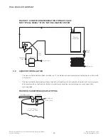
FIGURE 17: SUGGESTED REFRIGERATION PIPING OF VALVE
FOR TYPICAL MODEL “D” OR “DE” FRE-HEATER SYSTEM
3.2 AQUASTAT INSTALLATION
• The Aquastat bulb well should be installed in a
3
⁄
4
" circulation connection located on the top head, as illustrated
in Figure 18.
• The Aquastat bulb should be installed in the bulb well and the switch attached to the bulb well. A small amount
of thermal mastic on the Aquastat bulb will make it more sensitive to water temperature changes and is
recommended.
FIGURE 18: SUGGESTED AQUASTAT PIPING
19
Discharge
Line
Mueller
Fre-Heater
Condenser
To Receiver
Compressor
Suction Line
Check
Valve
1
⁄
4
"
Pilot
Line
Hot Water Line
Aquastat
Circulation
Connection
3
⁄
4
" or 1
1
⁄
2
" Water
Connection Tank