Mueller Fre-Heater D Series Скачать руководство пользователя страница 11

Mueller Model D Fre-Heater Installation and Operation Manual 

 Effective March 1, 1993

Part No. 8800430 


Revised November 6, 2019


2.4   INSTALLING WATER PIPING (CONTINUED)

A cold water bypass line should always be provided so the Fre-Heater(s) can be bypassed for service without 

shutting down the total water heating system.

Particular care should be paid to the hot water outlet connection on Fre-Heaters with 1

1

2

" FPT water connections. 

A pipe nipple (preferably brass) should be used so this joint can be securely tightened and retightened should it 

become loose. A copper pipe thread to sweat connector should not be used for this connection.

IMPORTANT: Be sure there are no leaks at the water connections that might cause the insulation to 

become wet.

IMPORTANT: To reduce the risk of excessive temperatures and pressures in this water heater, a pressure 

temperature relief valve has been installed by the manufacturer and should not be removed. This valve 

should be provided with a 

3

4

" drain line oriented so any discharge from the valve will exit within 6" above 

or at any distance below the structural floor and cannot contact any live electrical part. The discharge 

opening must not be blocked or reduced in size under any circumstances. Any additional protective 

equipment required by local codes must also be installed. In the event the pressure temperature relief 

valve is damaged or otherwise needs replacement, a combination pressure and temperature relief valve, 

certified by a nationally recognized testing laboratory that maintains periodic inspection of production 

of listed equipment, as meeting the requirements for ANSI Z21.22, “Relief Valves for Hot Water Supply 

Systems,” should be installed. The valve must be marked with a maximum set pressure of 150 psig for use 

on all Model “D” Fre-Heaters.

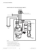
For commercial applications, an electrically operated water dump valve (Mueller Part No. 8824074) is provided to 

be installed on the outlet side (hot) of the Model “DE” Fre-Heater (see Figure 5). It should be screwed into a 

3

4

" FPT 

tee fitting and installed either at the tank outlet or at a more convenient location downstream of the Fre-Heater. 

If the Fre-Heater is a part of a multiple water heater system, a check valve should be installed in the hot water line 

following the dump valve. This valve is a part of the temperature regulating/limiting system for the Fre-Heater 

and should not be bypassed or ignored; however, an optional hot gas bypass can be used in place of the water dump 

valve. Since the water dump valve may discharge scalding water when the tank exceeds 180°F in temperature, 

precaution should be taken to divert or direct the flow of this valve to a safe place, preferably a drain. Piping should 

be supported on both sides of the valve to avoid damaging the valve body.

IMPORTANT: If a water mixing valve is installed in the system, make sure that check valves are in both 

hot and cold water lines. If this precaution is not taken, hot water may be drawn into the cold water 

system under certain system operating conditions.

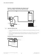
In some Fre-Heater systems, as in some standard water heating systems, thermal expansion of the water as it is 

being heated can be great enough to cause the pressure temperature relief valve to leak or open. Should this be a 

problem, we recommend the installation of a thermal expansion tank. See Section 6.0, “Appendix A.”‘

A “Therm-X-Trol” thermal expansion absorber or similar product can be piped in the system. For proper sizing of 

the expansion tank, please consult your supplier. Typically, an expansion tank having a volume of 10 or more gallons 

would be required for a Model “D” Fre-Heater with a water temperature of 140°F. See Appendix A for installation 

procedures. A thermal expansion absorber is provided with all dairy farm models.

7

Содержание Fre-Heater D Series

Страница 1: ...Part No 8800430 Effective March 1 1993 Revised November 6 2019 Model D Fre Heater INSTALLATION AND OPERATION MANUAL ...

Страница 2: ......

Страница 3: ...l Multiple Unit Parallel Plumbing for Fre Heaters 9 Figure 9 Fre Heater Piping Scheme 9 2 5 Refrigeration Connections 10 2 6 Heat Pumps 12 2 7 Ice Machines 12 2 8 Refrigerant Charge 12 2 9 Test Run 12 Figure 10 Typical Refrigeration Connections for a Single Condensing Unit and Single Circuit Piping 13 Figure 11 Typical Single Condensing Unit with Multiple Circuit Piping 13 Figure 12 Typical Dual C...

Страница 4: ...cing 24 5 2 Label No 8802732 Warning Pressure Relief Valve Must Be Installed 24 5 3 Label No 8801888 Warning Hot Water 24 5 4 Label No 8800996 Copper Conductor 25 5 5 Label No 3791 Hot 25 5 6 Label No 3792 Cold 25 5 7 Label No 9901403 In 25 5 8 Label No 9901404 Out 25 5 9 Label No 8800215 Pressure Relief 25 5 10 Label No 8822705 CSA LR 67608 and USK 25 5 11 Label No 8820623 Electrical Warning 25 5...

Страница 5: ... care In coastal areas where the air contains a high salt content the bright appearance of the Fre Heater can be maintained by rubbing it with oil or a light grease as soon as it is installed Abrasive cleaning materials or compounds should not be used on the outer jacket as it may scratch the surface IMPORTANT Fre Heaters are not normally suitable for use on capillary tube refrigeration systems Fr...

Страница 6: ...cuits Refrigeration Connection Size Per Circuit Refrig Capacity5 Water Connection Size Height Diameter Water Tank Capacity gal Approx Shipping Weight Lb Approx Loaded Weight Lb D 50 8823750 1 5 8 ODM 5 thru 4 3 4 FPT 54 213 4 50 225 600 D2 50 8823751 2 5 8 ODM 5 thru 4 3 4 FPT 54 213 4 50 225 600 D 80 8823780 2 3 4 ODM 1 thru 5 3 4 FPT 59 251 4 80 300 940 D 120 8823821 2 3 4 ODM 1 thru 7 5 11 2 FP...

Страница 7: ...ezing Particular attention should be directed to protecting the water piping going to and from the Fre Heater The Model D Fre Heater should be located as near as practical to the condensing unit s The Fre Heater should not be located where cooling tower or evaporative condenser water will be in continual direct contact with the exterior surface Careful planning of the Fre Heater location and plumb...

Страница 8: ... 11 2 WATER CONNECTION TANK 4 4 Approx 537 8 213 4 OD 3 4 FPT Cold Water Inlet and Drain Connection Anode 3 4 FPT Hot Water Outlet Connection Pressure Temperature Relief Valve 4 Approx 581 4 251 2 OD Anode 3 4 FPT Hot Water Outlet Connection 3 4 FPT Cold Water Inlet and Drain Connection Pressure Temperature Relief Valve 4 Approx Anodes 291 2 OD 615 8 11 2 FPT Hot Water Outlet Connection 11 2 FPT C...

Страница 9: ...T W Plug 1 5 FPT Hot Out 75 FPT W Plug Anode Plug 120 GALLON MODEL DHS AND DHSE FRE HEATER 75 P T Anode Plug R1 Out R1 In 1 25 MPT Cold In 75 FPT W Plug 1 25 FPT Hot Out 75 FPT W Plug Anode Plug 75 MPT Water Equalization Port R2 Out R2 In 75 P T Anode Plug R1 Out R1 In 1 5 FPT Cold In 75 FPT W Plug 1 5 FPT Hot Out 75 FPT W Plug Anode Plug 75 FPT Water Connections 625 ODM Refrigeration Connections ...

Страница 10: ...T The pipe from the HOT outlet should go to the conventional water heating system if one is being used Please see Figures 5 and 6 FIGURE 5 TYPICAL HOT WATER DUMP VALVE PIPING FIGURE 6 TYPICAL PLUMBING FOR FRE HEATER WATER CONNECTION 6 Hot Water Outlet Cold Water Inlet Check Valve Water Dump Valve N O N O N C Mueller Fre Heater Model ERS 120 E Only Mueller Fre Heater Hot Water Outlet Cold Water Inl...

Страница 11: ...el D Fre Heaters For commercial applications an electrically operated water dump valve Mueller Part No 8824074 is provided to be installed on the outlet side hot of the Model DE Fre Heater see Figure 5 It should be screwed into a 3 4 FPT tee fitting and installed either at the tank outlet or at a more convenient location downstream of the Fre Heater If the Fre Heater is a part of a multiple water ...

Страница 12: ...ter circulating pump suitable for the particular installation All pumps used in a Fre Heater water circulation system must be suitable for potable water use The Mueller hot water circulating pump Part No 8801091 is suitable for many installations Multiple Fre Heater installations may be piped in parallel if care is taken to assure equal flow through all of the Fre Heaters Parallel plumbing is usua...

Страница 13: ...RE HEATERS FIGURE 9 FRE HEATER PIPING SCHEME 9 Hot Water Outlet Pressure Temperature Relief Valve N O Gate Valve N O Drain Cold Water Inlet Mueller Fre Heater Check Valve Mueller Fre Heater Circulating Pump Conventional Water Heater Hot Water Loop Check Valve Mueller Fre Heater Cold Water Inlet Circulating Pump Booster Heater Loop Check Valve Mueller Fre Heater Cold Water Inlet ...

Страница 14: ...d excessive pressure drop in the lines CAUTION Refrigerant lines going to and from Mueller Fre Heaters could reach temperatures of 300 F Refrigerant lines must be insulated to prevent personal injury or other risks when near combustible substances The insulation will also add to the efficient operation of the Fre Heater If it is necessary to cut openings into the air conditioning or refrigeration ...

Страница 15: ...s a hot gas defrost valve an oil separator and or a discharge muffler in the compressor discharge line the Fre Heater must be installed downstream of those items See Figure 13 for an illustration of this In the event of extended compressor operation with little or no water usage it is possible to generate water temperatures that exceed the 210 F setting of the pressure temperature relief valve Thi...

Страница 16: ...e 14 for a refrigeration piping schematic 2 7 ICE MACHINES Generally a Fre Heater may be installed on water cooled ice machines and remote condenser air cooled ice machines These machines are usually equipped with large capacity receivers pump down controls and head pressure controls If a Fre Heater is to be installed on a self contained air cooled expansion valve refrigerant control ice machine t...

Страница 17: ...ly be used for a condensing unit having a capacity equal to or less than the single circuit rating as shown in Table 1 FIGURE 11 TYPICAL SINGLE CONDENSING UNIT WITH MULTIPLE CIRCUIT PIPING This piping configuration should only be used for a condensing unit having a capacity above the single circuit rating but not exceeding the multiple circuit rating as shown in Table 1 13 Suction Line Condenser M...

Страница 18: ...N WITH HOT GAS DEFROST VALVE OIL SEPARATOR AND OR DISCHARGE MUFFLER IN SYSTEM 14 Condenser Mueller Fre Heater Condenser Discharge Line Mueller Fre Heater Condenser Discharge Muffler To Receiver Compressor Oil Separator Suction Line Oil Return Line Hot Gas Defrost Valve This piping configuration should only be used for condensing units within the range of the per circuit ratings as shown in Table 1...

Страница 19: ... protect the user from possible electrical shock Use only copper conductors for these connections See Figure 15 for a wiring schematic A separate circuit for regulating the refrigerant heated water temperature must originate from the condensing unit power supply circuit It should be protected with a 5 A in line fuse This circuit connects the thermostats on the water heater in series with the water...

Страница 20: ...ame near the faucet at the time it is open The electrical heating element circuit contains controls that disconnect the electrical power to the element should the tank water temperature rise above 190 F This is a non resetting control so it will need to be reset each time the tank temperature reaches 190 F 2 12 MAINTENANCE In order to achieve the maximum life from Model D Fre Heaters the following...

Страница 21: ...led in Canada wiring between the Fre Heater and remote components must be field wired to conform to requirements of Part 1 of the Canadian Electrical Code 3 All enforced electrical codes must be followed during installation service and or operation of this equipment CONDENSING UNIT PILOT DUTY CIRCUIT ONLY 24 VOLTS 10 WATT HI LIMIT THERMOSTAT HEATING ELEMENT 4500 W CUSTOMER SUPPLIED FUSED DISCONNEC...

Страница 22: ...ompressor The valve should be installed in a vertical position coil up and supported by hangers A check valve must be installed in the refrigerant line between the Mueller Fre Heater and the tee as shown in Figure 17 Suggested refrigeration piping of the valve in a typical Model D or DE Fre Heater system is illustrated in Figure 17 See Table 4 for check valve sizing Piped in the suggested manner t...

Страница 23: ...nection located on the top head as illustrated in Figure 18 The Aquastat bulb should be installed in the bulb well and the switch attached to the bulb well A small amount of thermal mastic on the Aquastat bulb will make it more sensitive to water temperature changes and is recommended FIGURE 18 SUGGESTED AQUASTAT PIPING 19 Discharge Line Mueller Fre Heater Condenser To Receiver Compressor Suction ...

Страница 24: ...The electrical components should be wired in accordance with the diagram in Figure 19 FIGURE 19 WIRING OF ELECTRICAL COMPONENTS 3 4 CHECKOUT AND TEST RUN On completion of the Fre Heater installation the refrigeration system should be checked for leaks and proper charge The water system should be checked for leaks and trapped air and the solenoid valve should be checked for proper operation To chec...

Страница 25: ...IONS CHART TABLE 4 DISCHARGE CHECK VALVE SIZING 21 G A B Compressor Discharge Reclaim Condenser Normal Condenser C 1 4 SAE Suction Connection E D 2 56 F Part No Port Size in Connection ODF Solder in A in B in C in D in E in F in G in 8827286 5 8 5 8 5 00 4 36 3 22 3 22 79 3 84 50 8827284 11 4 13 8 6 87 6 94 4 19 4 19 2 38 4 35 97 Part No Connection Size Maximum Capacity 8820255 5 8 ODF 4 Tons 8820...

Страница 26: ... Port Size 5 8 3 4 11 4 2 5 8 3 4 11 4 2 Evaporator Temp F 40 3 7 8 0 23 4 56 2 5 2 11 2 33 6 81 0 30 3 6 7 8 22 8 54 9 5 1 10 9 32 8 78 7 20 3 6 7 6 22 2 53 4 4 9 10 7 31 9 76 6 10 3 5 7 4 21 6 52 0 4 8 10 3 31 0 74 5 0 3 4 7 2 21 0 50 4 4 7 10 1 30 2 72 3 10 3 3 7 0 20 3 48 9 4 5 9 8 29 3 70 1 20 3 1 6 7 19 7 47 3 4 4 9 4 28 3 67 8 30 3 0 6 5 19 0 45 6 4 2 9 1 27 3 65 4 40 2 9 6 3 18 3 44 0 4 1 ...

Страница 27: ...pacity is unknown NOTES To use the above tables all compressor sizes must be converted to tons Stay with refrigeration tonnages listed in Table 1 Model D Fre Heater Technical Specifications when planning applications and estimating heat recovery The above tables are averages based on 1 gpm or less flow rate and the average heat recovery of numerous installations The actual heat recovery on any giv...

Страница 28: ...32 WARNING AVERTISSEMENT PRESSURE RELIEF VALVE LIMITING THE PRESSURE TO 1000kPA MUST BE INSTALLED UNE SOUPAPE DE SÉCURITÉ LIMITANT LA PRESSION À 1000 kPA DOIT ÊTRE INSTALLÉ 8801888 WARNING PELIGRO HOT WATER CAN PRODUCE THIRD DEGREE BURNS IN 6 SECONDS AT 60 C 140 F IN 30 SECONDS AT 54 C 130 F THERMOSTATS WERE FACTORY SET AT 60 C 140 F PLEASE CONTACT QUALIFIED SERVICE PERSONNEL FOR ADJUSTMENTS EL AG...

Страница 29: ...EF 5 10 LABEL NO 8822705 CSA LR 67608 AND USK 5 11 LABEL NO 8820623 ELECTRICAL WARNING 25 HOT 3791 COLD 3792 IN 9901403 OUT 9901404 PRESSURE RELIEF 8800215 7901 HOT 3791 COLD 3792 IN 9901403 OUT 9901404 PRESSURE RELIEF 8800215 7901 HOT 3791 COLD 3792 IN 9901403 OUT 9901404 PRESSURE RELIEF 8800215 7901 HOT 3791 COLD 3792 IN 9901403 OUT 9901404 PRESSURE RELIEF 8800215 7901 HOT 3791 COLD 3792 IN 9901...

Страница 30: ...alve installation temperature and pressure protective equipment is required by local codes but not less than a combination temperature and pressure relief valve device certified as meeting the requirements in the listing requirements for ANSI Z21 22 Relief Valves For Hot Water Supply Systems by a nationally recognized testing laboratory that maintains periodic inspection of the production of liste...

Страница 31: ...ER FOR BRITISH COLUMBIA OH4249 1 CRN NUMBER FOR ALL OTHER PROVIDENCES OH8902 5 IMPORTANT THIS EQUIPMENT CONTAINS A HOLDING CHARGE OF DRY NITROGEN GAS SLOWLY RELEASE PRESSURE THROUGH SERVICE PORTS OR SCHRADER VALVES BEFORE REMOVING FITTINGS EVACUATE THE SYSTEM TO 500 MICRONS BEFORE CHARGING WITH REFRIGERANT DISCARD THIS TAG UPON CHARGING SYSTEM WITH REFRIGERANT AND APPLY A SYSTEM REFRIGERANT SPECIF...

Страница 32: ...elief valve is intended as a safety device and should not be relied upon to perform this function The following diagram shows the proper installation method for a thermal expansion tank A thermal expansion tank Mueller Part No 8805175 is available and will work well for this application Please Note One thermal expansion tank Part No 8805175 is required for every 120 gallon Fre Heater and or water ...

Страница 33: ......

Страница 34: ...1600 West Phelps Street Springfield Missouri 65802 U S A DFE Service 1 800 756 5991 DFETechService paulmueller com 1 800 MUELLER WWW PAULMUELLER COM 2019 Paul Mueller Company 8800430 ...

Отзывы: