hydro-guard
®
hg-8 Warm Climate Flushing System
Installation Instructions
2
Please read and retain this manual
for future reference, training,
troubleshooting, and maintenance.
Site Evaluation
Each Hydro-Guard
®
Unit installation
is unique and will require a minimum
of advance planning. Prior to the
installation of the device, the drainage
patterns for the intended installation
location should be reviewed. The
overview
The Hydro-Guard
®
HG-8 Warm
Climate Unit, is the industry’s
only Sub-Surface Discharge,
programmable flushing apparatus
(patent pending). This Unit is
suitable for year-round use in warm
to moderate climates. This Automatic
Flushing System has been designed,
engineered, and manufactured to
provide outstanding dependability
and performance.
drainage pattern must permit
discharged water to flow away from
the Hydro-Guard
®
Unit. Discharged
water flushed from the Hydro-Guard
®
Unit must be routed away from the
device. (see Typical Installation
illustration).
The recommended final discharge
points may include a storm drain,
drainage or retention pond, or a
storm swale.
General
2. Turn off the service line feed.
3. Excavate a suitably sized ditch
ensuring it is connected on one
side to the utility’s service line
trench. Remove any debris that
might create uneven pressure on
the Unit. Compact the bottom of the
hole in order to minimize settling
Hydro-Guard
®
HG-8 Warm
climate Flushing unit
The Hydro-Guard
®
HG-8 Warm
Climate Flushing System is housed
in a Mueller
®
Meter Box that is
approximately 21 inches in diameter.
The bury depth options for this design
are 36” or 42”. The box is constructed
with low lead NTP male threads and
is to be placed by the contractor at
a location agreed upon by the end
user. The box features brass inlet and
outlet connections that will route water
from the water utility’s potable water
distribution line through the HG-8’s
flushing components, and discharge
through a discharge service routed to
an acceptable point of discharge (i.e.,
a storm sewer, swale, storm pond,
etc.). The flushing assembly can be
raised and removed for maintenance
and repair and then lowered back
down into the box to center it to
service. An optional medium density
foam insulation pad is available for
frost protection.
WARNING: Proper lifting,
loading/unloading tools and
techniques must be followed
when handling this device.
Damage to working components
can occur if dropped.
1. Remove the Hydro-Guard
®
Unit
from its packaging and inspect for
possible damage during shipping.
after installation. Place #57 stone.
Then, place non-compacted clean
bedding material within the bottom of
the hole. Provide a bed of crushed
gravel approximately 6 inches thick
or place bricks or cement blocks
below the pit to allow for drainage
and provide support.
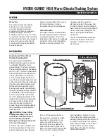
InstallatIon
!
typical installation
2”
Double
check
Valve
3
/
8
” Poly tubing
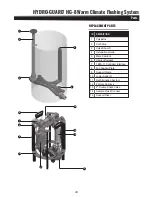
Dechlorination System
tB0S-11 controller Interface
Lower Alignment Plate
Alignment Rail
Lifting Hoop
cartridge Alignment Plate


