background image

4. Starting up and shutting down the heater

4.1. Heating phase


Set the main switch to position '1', and the work mode switch to heating (Grzanie). The burner is actuated. When the 
temperature of 40 °C is reached, the fan switches on automatically. When the exhaust temperature reaches 80 °C, the 
burner is switched off, and the exchanger enters a cooling cycle. The cycle is repeated after the burner is actuated again 
by the limit thermostat. 

WARNING!


Before switching off the main switch, make sure that the heat exchanger has cooled down sufficiently. This will extend the 
heater lifetime. 
The actuation of the Limit 2 thermostat may indicate damage to the heater. If the situation repeats itself, contact the 
vendor service department. 

4.2. Shutting the heater down


Set the work mode switch to position '0' - 

burner off (Palnik wyłączony), the ventilator shall continue operating until the 

exchanger cools down sufficiently, whereupon it will shut off automatically. 
The ventilator may turn on again - this does not indicate of a flaw. 
In order to shut down the entire heater, set the main switch to position '0'. 

4.3. LIMIT 2 safety thermostat


When the air temperature exceeds 80 °C, the Limit thermostat shall shut down the burner, and later it will turn it on again 
automatically. If the thermostat does not operate properly and if the air temperature rises to 100 °C, the main safety 
thermostat Limit 2 shall switch the burner off. The thermostat diode on the electric cabinet shall light up (only 400 V 
models). In such a case, wait for a few seconds for the fan to cool down the heat exchanger, and then press the 
thermostat button located under the cover cap on the thermostat cabinet. 

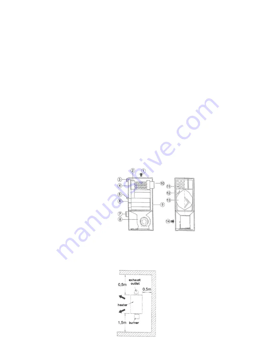
5. Heater diagram

1. Air outlet
2. Heat exchanger
3. Thermostat cabinet
4. Exchanger maintenance opening
5. Combustion chamber window
6. Burner assembly plate
7. Electric cabinet
8. Fan
9. Heater frame
10. Exhaust gas outlet
11. Insulated housing
12. Air divisions
13. Combustion chamber
14. Air inlet

6. Heater placement

The figure below shows the arrangement of the heater within a room. The indicated distances to walls and other items are 
minimum recommended values. 

Содержание MP25

Страница 1: ...AIR HEATER UNIT TYPES M MP Original instruction manual v 08 2015 ...

Страница 2: ...ssment of human responses to contact with surfaces Hot surfaces EN ISO 13857 2008 Safety of machinery Safety distances to prevent hazard zones being reached by upper and lower limbs EN ISO 14159 2008 Safety of machinery Hygiene requirements for the design of machinery EN 60335 1 2002 A14 2010 Household and similar electrical appliances Safety General requirements EN 55014 1 2006 A1 2009 Electromag...

Страница 3: ... it Failure to observe remarks indicated with this symbol may lead to damage to the heater or even to personal injury IMPORTANT This is an indication of the requirement to read the information found after it very carefully as this will contribute to safe use of the device 1 3 General indications Air heaters with heat exchangers may be used in rooms in which people remain WARNING Never install the ...

Страница 4: ... casing is made of painted sheet steel and possesses a thermal insulation layer made of non flammable insulation wool with an aluminium layer Under the combustion chamber in the ventilation part there is the ventilator The ventilation chamber is protected by a mesh Furthermore the heater is equipped with the following safety devices ventilator thermostat automatically switches the ventilator on an...

Страница 5: ...lator may turn on again this does not indicate of a flaw In order to shut down the entire heater set the main switch to position 0 4 3 LIMIT 2 safety thermostat When the air temperature exceeds 80 C the Limit thermostat shall shut down the burner and later it will turn it on again automatically If the thermostat does not operate properly and if the air temperature rises to 100 C the main safety th...

Страница 6: ...vice safety thermostat MV fan TA room thermostat F1 fan fuse F2 burner fuse 400 V supply version IG main switch M fan TV FUN fan thermostat 35 C TLR contactor RT thermal relay BR burner TS overheat thermostat 110 C TSS burner shutdown thermostat 80 C TP room thermostat L coil FO fuse INT device function switch SR power supply diode STV fan failure diode STS overheat diode ...

Страница 7: ...he burner A B C D E Weight kg mm mm mm mm mm MP25 1440 530 660 1225 150 140 M25 130 MP35 148 M35 130 MP50 1650 640 870 1390 180 210 M50 138 MP65 220 M65 200 MP80 1800 750 1000 1525 200 315 M80 210 MP100 325 M100 305 MP125 2020 800 1230 1760 250 480 M125 450 MP150 490 9 Sample nameplate on the back housing of the device ...

Страница 8: ... 17 0 17 0 24 0 24 0 24 0 24 0 33 0 33 0 33 Volume m3 0 08 0 08 0 08 0 08 0 22 0 22 0 22 0 22 0 32 0 32 0 32 0 32 0 46 0 46 0 46 Mean exhaust gas temp C 195 195 228 228 196 196 229 229 196 196 228 228 229 229 241 Fuel cons l h 1 8 3 0 2 1 3 3 3 5 3 9 3 5 3 9 4 0 6 4 4 0 6 4 5 8 8 0 5 8 8 0 7 9 9 8 7 9 9 8 9 7 12 5 9 7 12 5 12 5 16 0 12 5 16 0 16 5 19 0 Air output m3 h 2170 2100 2860 2800 4100 4700...

Отзывы: