13
Premier GP-9 Diesel Engine Operating Instructions
3. Once the motor mount screw has been removed, pull the motor away from
the truck block and lightly coat the motor worm gear and bronze drive gear (in
the truck block) with grease.
4. Reassemble the truck and motor, being careful not to pinch any wires
between the truck block and motor mount.
5. After repeating the procedure for the other motor, reassmble the chassis and
body, being careful that the wire harnesses are not caught between the chassis
and body and reinstall the chassis screws.
Lubricate the outside truck block idler and drive gears with grease. Use the
diagram shown in Figure 7 above as a guide and add grease to the points
marked with a “G.”
Periodically check the locomotive wheels and pickups for dirt and buildup,
which can cause poor electrical contact and traction as well as prematurely
wear out the neoprene traction tires.
Traction Tire Replacement Instructions
Your locomotive is equipped with two neoprene
rubber traction tires on each powered truck block.
While these tires are extremely durable, you may
need to replace them at some point.
First, remove the truck sides from the truck block.
To do this, turn your engine upside down. If there
are visible Phillips screw heads between the truck
frame and truck block (see Fig. 8), go to step A. If
not, go to step B.
A. Remove the two Phillips screws that attach the
truck sides to the truck block.
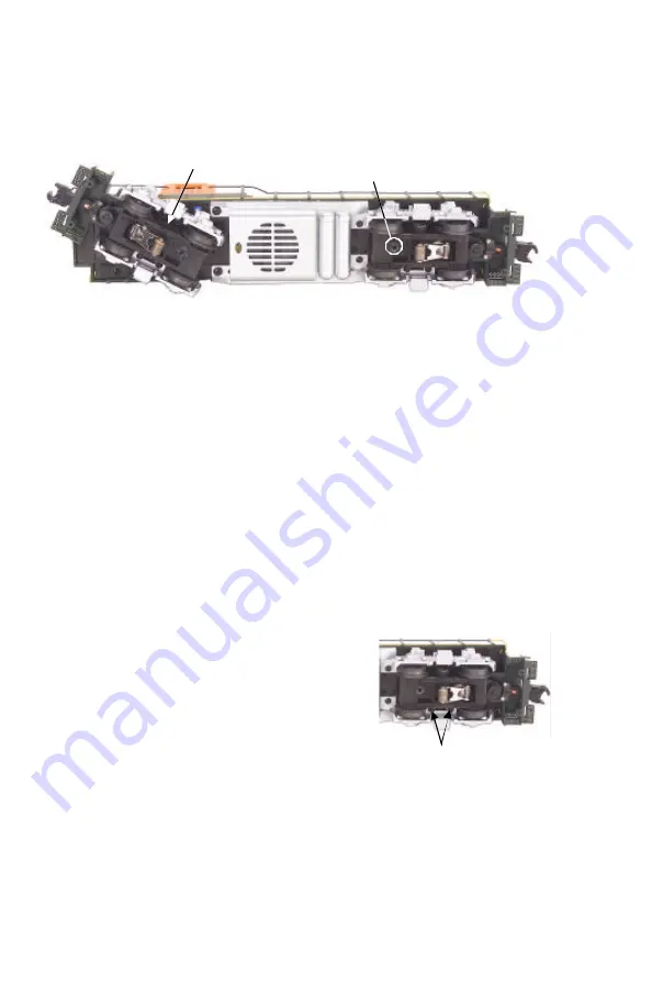
Grease Idler Gear (G)
Motor Mount Screw
Figure 7. Locations of Greasing Points on the Locomotive
Truckside
Screws
Figure 8. Truckside
Mounting Screws to Access
the Traction Tires


