MTD OEM-190-627 Скачать руководство пользователя страница 5

5

SECTION 2:  TO THE OWNER 

Model 627 42-inch two-stage snow thrower is designed for use on 600-series lawn tractors manufactured in 
1996 or later ONLY
. It will NOT fit nor operate properly or safely on ANY other tractor. It will NOT fit on any 
FastAttach™ compatible tractor.

NOTE:  If your 600-series lawn tractor was manufactured prior to 1996, model 627 snow thrower attachment can be
mounted on the tractor with special instructions and minor modifications to the tractor. Phone our Customer Support
Department as instructed on page 2 for details. 

NOTE: References to LEFT and RIGHT indicate the left and right sides of the tractor when facing forward in the
operator’s position. Reference to the FRONT indicates the grille end; to the REAR the drawbar end.

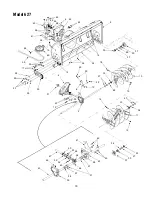
SECTION 3:  CONTENTS OF CARTON

Before beginning installation, remove all parts from the carton to make sure everything is present. Carton contents
are listed below and shown in Figure 3. Part numbers are shown in parentheses.

One Auger Housing Assembly

One Undercarriage Assembly with 
Upper V-belt (754-0449) & Lower V-belt (754-0330)

One Support Carriage Assembly

One Chute Directional Control with Tilt Lever

One Lift Handle Assembly with Cable

One Upper Chute Crank Rod

Two Self-adhesive Reflectors (730-3000)

Three Cable Ties (725-0157)

One Extension Spring (732-0626)

Two Spare Shear Bolts (710-0890A)
& Hex Lock Nuts (712-0429)

One Flat Washer (736-3019)

One Hairpin Clip (714-0145)

Two Hex Screws (710-0376)

Two Belleville Washers (736-0242)

Two Lock Washers (736-0119)

Two Hex Nuts (712-3010)

Two 1¼-inch Cotter Pins (714-0470)

One ¾-inch Cotter Pin (714-0507)

Figure 3

Chute Directional Control

Undercarriage Assembly

Auger Housing Assembly

Lift Handle Assembly

Self-adhesive

Cable

Spare Shear Bolts

Upper Chute Crank Rod

Support Carriage Assembly 

Extension

¾-inch

1¼ Cotter Pins

Hex Screws,

Reflectors

Spring

Ties

Belleville Washers,

Lock Washers

and Hex Nuts

Cotter Pin

& Hex Lock Nuts

Flat Washer

& Hairpin Clip 

with Upper V-belt & Lower V-belt 

with Tilt Lever

With Cable

Содержание OEM-190-627

Страница 1: ...Attach compatible tractors Check your tractor s right fender for the FastAttach label before attempting to mount this attachment NOTE This snow thrower attachment will NOT fit on ANY 800 series garden tractors regardless of the tractor s FastAttach compatibility 42 inch Snow Thrower Attachment Operator s Manual For 600 series Lawn Tractors MTD PRODUCTS INC P O BOX 368022 CLEVELAND OHIO 44136 9722 ...

Страница 2: ...er of the equipment in the space below Figure 1 An example of what the model plate will look like is shown below CALLING CUSTOMER SUPPORT If you have difficulty assembling this product or have any questions regarding the controls operation or maintenance of this unit please call the Customer Support Department Call 1 330 220 4MTD 4683 or 1 800 800 7310 to reach a Customer Support representative Pl...

Страница 3: ...hich could be thrown by the auger impeller 2 Always wear safety glasses or eye shields during operation and while performing an adjustment or repair to protect your eyes Thrown objects which ricochet can cause serious injury to the eyes 3 Do not operate without wearing adequate winter outer garments Do not wear jewelry long scarves or other loose clothing which could become entangled in moving par...

Страница 4: ... bolts and screws for proper tightness at frequent intervals to keep the machine in safe working condition Also visually inspect machine for any damage 4 Do not change the engine governor setting or over speed the engine The governor controls the maximum safe operating speed of the engine 5 Snow thrower shave plates and skid shoes are subject to wear and damage For your safety protection frequentl...

Страница 5: ...ts are listed below and shown in Figure 3 Part numbers are shown in parentheses One Auger Housing Assembly One Undercarriage Assembly with Upper V belt 754 0449 Lower V belt 754 0330 One Support Carriage Assembly One Chute Directional Control with Tilt Lever One Lift Handle Assembly with Cable One Upper Chute Crank Rod Two Self adhesive Reflectors 730 3000 Three Cable Ties 725 0157 One Extension S...

Страница 6: ...nd allow clearance for positioning the support carriage 3 Remove the hex screws lock washers and hex nuts from the both sides of the rear of the support carriage assembly 4 Place the support carriage assembly between the tractor s front tires so that the large notch on both sides of the support carriage straddles the tractor s front pivot bar See Figure 5 5 Position the rear of the support carriag...

Страница 7: ...haped rod found on the front right will suspend through the opening in the right side of the undercarriage NOTE The rear lift links See Figure 8 are unaffected by this assembly and not used in any regard by the snow thrower attachment Both can be ignored 5 With the undercarriage s side plates positioned to the inside of the support carriage mounted earlier reinsert the carriage bolts removed in st...

Страница 8: ... center of each of the auger assembly s lower lift links and reinsert the clevis pins just removed through these aligned holes 6 Secure the vertical lift links to the lower lift links by fastening with the flat washers and hairpin clips also removed in Step 4 See Figure 11 7 Remove the hex screws flat washers and crown nuts from the rear portion of each lower lift link 8 Grasp the auger housing su...

Страница 9: ...ower chute crank rod upward and secure it to the upper chute crank rod with the inch cotter pin provided See Figure 14 5 Fasten the chute tilt cables to the chute directional control with the three cable ties provided Pull the cable ties until they re snug and trim off any excess Routing the Upper Drive Belt 1 Make sure that the V side of the upper drive belt is seated firmly in the upper portion ...

Страница 10: ...roceed as follows 1 Place the tractor s lift lever in the lowest reachable engagement notch 2 Locate the adjustable lift link and thread it upward as far as possible 3 Insert the end of the tractor s adjustable lift link through the hole found in the undercarriage s engagement bracket See Figure 17 4 Secure the adjustable lift link to the engagement bracket with the flat washer and hairpin clip pr...

Страница 11: ...lt lever forward or rearward into a desired position The direction which snow is thrown can be changed by rotating the discharge chute with the chute crank Turn the chute crank clockwise to rotate the chute and discharge snow to the left Crank it counterclockwise to rotate the chute and discharge snow to the right SECTION 6 OPERATION This snow thrower attachment is capable of displacing snow and c...

Страница 12: ...d into the sidewalls of your tractor s tires Use drift cutters to aid in displacing snow through deep drifted areas NOTE None of the kits in the table are included as standard equipment with snow thrower attachment OEM 190 627 Call our Customer Support Department as instructed on page 2 of this manual for availability and information regarding these kits SECTION 7 ADJUSTMENTS WARNING Never attempt...

Страница 13: ...ement notch third notch down 2 Locate the control rod found to the inside of the engagement plate on the undercarriage assembly See Figure 20 3 Remove the hairpin clip and flat washer from the ferrule found at the rear of the control rod See Figure 20 4 Remove the ferrule from the hole in the engagement plate and slide the control rod as far forward as it will go in the slot in the idler bracket S...

Страница 14: ...htening the hex nuts Figure 22 SECTION 8 LUBRICATION Auger Shaft At least once a season remove the shear bolts on the auger shaft Oil or spray lubricant inside and on the plastic bearings on the shaft and near the holes where the shear bolts were removed before reattaching them See Figure 23 Figure 23 Chute Directional Control The spiral on the end of the lower chute crank the base of the discharg...

Страница 15: ...15 NOTES ...

Страница 16: ...1 103 85 75 71 72 103 81 78 76 32 74 67 28 9 82 1 4 2 8 23 24 70 79 68 9 15 15 14 14 7 8 10 32 19 12 6 22 19 46 8 Hook Spring Ref 13 Here 13 3 16 45 17 21 25 26 27 29 30 31 34 35 37 38 39 40 41 20 20 42 17 43 73 44 5 21 104 105 37 42 42 20 20 5 53 102 106 107 108 109 110 77 33 69 9 15 32 111 20 40 33 61 77 113 17 112 114 77 33 36 36 115 116 117 Model 627 118 ...

Страница 17: ... 1313C Chute Tilt Cable Guide 59 731 1320 Upper Chute 60 736 0231 Flat Washer 344 x 1 125 x 125 61 736 0242 Bell Washer 34 x 872 62 736 0451 Saddle Washer 32 x 93 63 746 0929 Chute Cable w Clip 54 5 64 746 0928 Chute Cable 54 5 65 784 5594 Cable Bracket 66 784 5604 Chute Tilt Handle 67 683 0298 Lift Bracket Assembly 68 703 2728A Snow Thrower Lift Bracket 69 710 3008 Hex Cap Screw 5 16 18 x 75 70 7...

Страница 18: ...3 12 29 2 22 29 12 22 27 33 18 19 10 27 33 11 19 18 33 27 30 37 30 27 33 37 14 34 26 26 61 60 62 19 5 64 26 8 65 63 59 39 58 51 58 57 57 43 45 46 49 48 54 43 55 50 47 56 40 42 42 41 69 69 36 69 36 68 67 6 15 66 3 38 31 Model 627 ...

Страница 19: ...de Shoe 36 711 0469 Spacer 75 x 125 x 5 37 784 5618 Hex Bearing Housing 1 0 38 784 0402 Skid Plate 39 618 0123 RH Reducer Housing Incl Ref 57 58 40 618 0124 LH Reducer Housing Incl Ref 57 58 41 703 2733 Housing Brace Plate 42 710 0642 Self Tapping Screw 1 4 20 x 75 43 711 1395 Spiral Axle 41 5 44 714 0161 Hi Pro Key 3 16 x 5 8 45 715 0143 Spring Spirol Pin 25 x 1 25 46 717 0528 Worm Gear 20 tooth ...

Страница 20: ...ate manufacturer s warranty Please refer to the applicable manufacturer s warranty on these items b Routine maintenance items such as lubricants filters blade sharpening and tune ups or adjustments such as brake adjustments clutch adjustments or deck adjustments and normal deterioration of the exterior finish due to use or exposure c Log splitter pumps valves and cylinders have a sepa rate one yea...

Отзывы: