background image

3

SECTION 1:  IMPORTANT SAFE OPERATION PRACTICES

WARNING:

This symbol points out important safety instructions which, if not followed, could endanger

the personal safety and/or property of yourself and others. read and follow all instructions in this manual
before attempting to operate your snow thrower. Failure to comply with these instructions may result in
personal injury. When you see this symbol, heed its warning.

DANGER:

Your snow thrower was built to be operated according to the rules for safe operation in this

manual. As with any type of power equipment, carelessness or error on the part of the operator can result
in serious injury. If you violate any of these rules, you may cause serious injury to yourself or others.

WARNING:

The Engine Exhaust from this product contains chemicals known to the State of

California to cause cancer, birth defects or other reproductive harm.

Training

Read this operator's manual carefully in its entirety
before attempting to assemble or operate this
machine. Be completely familiar with the controls
and the proper use of this machine before
operating it. Keep this manual in a safe place for
future and regular reference and for ordering
replacement parts.

Never allow children under 14 years old to operate
a snow thrower. Children 14 years old and over
should only operate snow thrower under close
parental supervision. Only persons well
acquainted with these rules of safe operation
should be allowed to use your snow thrower.

No one should operate this unit while intoxicated or
while taking medication that impairs the senses or
reactions.

Keep the area of operation clear of all persons,
especially small children and pets.

Exercise caution to avoid slipping or falling,
especially when operating in reverse.

Preparation

Thoroughly inspect the area where the equipment
is to be used and remove all door mats, sleds,
boards, wires and other foreign objects.

Disengage all clutches and shift into neutral before
starting engine.

Do not operate equipment without wearing
adequate winter outer garments. Do not wear
jewelry, long scarfs or other loose clothing which
could become entangled in moving parts. Wear
footwear which will improve footing on slippery
surfaces.

Before working with gasoline, extinguish all
cigarettes and other sources of ignition. Check the
fuel before starting the engine. Gasoline is an
extremely flammable fuel. Do not fill the gasoline
tank indoors, while the engine is running, or until
engine has been allowed to cool at least two
minutes. Replace gasoline cap securely and wipe
off any spilled gasoline before starting the engine
as it may cause a fire or explosion.

Use a grounded three wire plug-in for all units with
electric drive motors or electric starting motors.

Adjust collector housing height to clear gravel or
crushed rock surface.

Never attempt to make any adjustments while
engine is running (except where specifically
recommended by manufacturer).

Let engine and machine adjust to outdoor
temperature before starting to clear snow.

Always wear safety glasses or eye shields during
operation or while performing an adjustment or
repair, to protect eyes from foreign objects that
may be thrown from the machine in any direction.

Operation

Do not put hands or feet near or under rotating
parts. Keep clear of discharge opening and auger
at all times.

Exercise extreme caution when operating on or
crossing gravel drives, walks, or roads. Stay alert
for hidden hazards or traffic.

After striking a foreign object, stop the engine,
remove wire from spark plug, and thoroughly
inspect the snow thrower for any damage. Repair
the damage before restarting and operating the
snow thrower.

If the snow thrower should start to vibrate
abnormally, stop the engine and check
immediately for the cause. Vibration is generally a
warning of trouble.

Stop engine whenever you leave the operating
position, before unclogging the collector/impeller
housing or discharge guide, and making any
repairs, adjustments, or inspections. Never place
your hand in the discharge or collector openings.
Use a stick or wooden broom handle to unclog the
discharge opening.

Take all possible precautions when leaving the unit
unattended. Disengage the collector/impeller, shift
into neutral, stop the engine, and remove the key.

When cleaning, repairing, or inspecting, make
certain collector/impeller and all moving parts have

Содержание E173

Страница 1: ...ne s exhaust system is equipped with a spark arrester meeting applicable local or state laws if any If a spark arrester is used it should be maintained in effective working order by the operator In the State of California the above is required by law Section 4442 of the California Public Resources Code Other states may have similar laws Federal laws apply on federal lands A spark arrester for the ...

Страница 2: ... Customer Support Department or an authorized dealer You can locate the model number by standing behind the unit in the operating position and looking down at the dash panel A sample model plate is explained below For future reference please copy the model number and the serial number of the equipment in the space below CALLING CUSTOMER SUPPORT If you have difficulty assembling this product or hav...

Страница 3: ...r other loose clothing which could become entangled in moving parts Wear footwear which will improve footing on slippery surfaces Before working with gasoline extinguish all cigarettes and other sources of ignition Check the fuel before starting the engine Gasoline is an extremely flammable fuel Do not fill the gasoline tank indoors while the engine is running or until engine has been allowed to c...

Страница 4: ...as wheel weights counter weights cabs etc Never operate the snow thrower without good visibility or light Always be sure of your footing and keep a firm hold on the handles Walk never run Muffler and engine become hot and can cause a burn Do not touch Maintenance And Storage Check shear bolts engine mounting bolts etc at frequent intervals for proper tightness to be sure equipment is in safe worki...

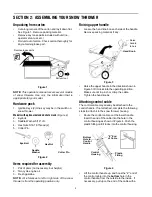
Страница 5: ...position only Raising upper handle Loosen the hand knob on each side of the handle Remove packing material if any Figure 3 Raise the upper handle in the direction shown in Figure 3 till it clicks into the operating position Make sure not to pinch or crimp the cable Tighten the hand knobs Attaching control cable The control cable may already be attached to the control handle If not attached complet...

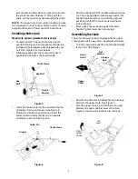
Страница 6: ...and insert the cotter pin Bend ends of cotter pin in opposite directions to secure See Figure 6 Figure 6 Secure eyebolt with 5 16 saddle washer and hex nut The cupped side of washer goes against the handle Adjust lower hex nut until the eyebolt is positioned so that the chute crank turns freely does not bind Move upper hex nut down against the lower handle Tighten lower hex nut securely Assembling...

Страница 7: ...th a 120V power source Plug for Electric Start Optional Requires use of a two prong outdoor extension cord and a 120V power source Spark Plug Cover Spark plug located under the cover Auger Control Handle Located on the upper handle the auger control handle is used to engage and disengage the augers The snow thrower is designed to be propelled by the rotation of the augers Pull the control handle b...

Страница 8: ...ared Release the auger control handle to stop the snow throwing action and the forward motion Figure 11 Stopping engine Run the engine for a few minutes before stopping to help dry any moisture on the engine To stop engine Turn ignition key to OFF position and remove it from the snow thrower IMPORTANT Keep the ignition key in a safe place Engine will not start without it Wipe all snow and moisture...

Страница 9: ...iodic adjustment of the belt tension may be required due to normal stretch and wear on the belt Adjust the belt tension following instructions below if the augers seem to hesitate while turning although engine maintains the same speed The upper hole in the control handle provides adjustment for belt tension To adjust disconnect the Z end of control cable from the bottom hole in the control handle ...

Страница 10: ...ked periodically There are two wearing edges and the shave plate can be reversed See Figure 18 Remove the four carriage bolts and hex lock nuts which attach it to the snow thrower housing Install new shave plate making sure the heads of the carriage bolts are on the inside of the housing Adjust the shave plate according to procedure in the Making Adjustments section of this manual Tighten securely...

Страница 11: ...should be checked at least once each season Periodically check all fasteners and make sure these are tight Follow the maintenance schedule given below to get quality performance from your snow thrower for a long time Lubrication Lubricate pivot points on the control handle and the extension spring at the end of the clutch cable with a light oil once every season and before storage of the snow thro...

Страница 12: ...ate as instructed above with a light oil Follow Storage instructions found in the separate Engine Operator s Manual Preparing the engine for storage properly is important to prevent problems next season Store in a clean dry area Block the snow thrower up so it is not resting on the rubber auger blades NOTE When storing any type of power equipment in an poorly ventilated or metal storage shed care ...

Страница 13: ...by an authorized service dealer Engine overheats 1 Gasoline and oil not mixed correctly 2 Carburetor out of adjustment 1 Drain fuel tank and refill with proper fuel mixture 2 Refer to engine manual get the carburetor adjusted by an authorized service dealer Loss of power 1 Spark plug wire loose 2 Vent in gas cap plugged 3 Exhaust port plugged 1 Connect and tighten spark plug wire 2 Clear vent 3 Cl...

Страница 14: ...14 SECTION 10 PARTS LIST FOR MODELS 140 THROUGH E173 ...

Страница 15: ... 21 732 0357A Extension Spring 22 736 0108 Flat Washer 23 736 0119 Lock Washer 25 736 0176 Flat Washer 26 736 0159 Washer 27 736 0326 Flat Washer 28 736 0329 Lock Washer 30 741 0600 Ball Bearing 31 746 0910A Cable Clutch 32 748 0234 Spacer 33 749 0796 Handle Lower 34 756 0313 Flat Idler 35 784 5174 Bearing Cup 36 784 5176 Cover Belt 37 784 5175B Idler Brake Bracket 38 684 0114 Blower Housing 39 78...

Страница 16: ...s y Control 8 749 0705 Handle Upper 9 736 0451 Saddle Washer Models 140 150 E150 and E151 Ref No Part No Part Description 1 710 1270 Oval C Sink L Screw 2 710 0487 Carriage Bolt 3 712 0324 Insul Lock Nut 4 720 0295 Grip Foam 5 720 0284 Knob Handle 6 725 0157 Tie Cable 7 736 0451 Washer Saddle 8 746 0883 Body Lever Control 9 747 0956 Handle Ass y Control 10 749 0711A Handle Upper Models 142 E152 E1...

Страница 17: ...3 731 0702 Shroud 14 731 1133B Plug 15 736 0119 Lock Washer 16 736 0185 Flat Washer 17 736 0225 Internal Lock Washer 18 736 0400 Flat Washer 20 741 0475 Bushing 21 784 5178A Bracket Chute Crank 22 784 5344 Crank Assembly Chute 23 714 0111 Cotter Pin 24 747 0737 Chute Crank Upper 26 684 0126 Chute Crank Lower 27 750 0785 Spacer 29 735 0234 Grommet Rubber 30 747 0697 Eyebolt Chute Crank 31 712 3010 ...

Страница 18: ...1 725 0201 Key Ignition 12 725 1425 Switch 13 726 0100 Cap Push 14 731 1087 Shroud Black 15 731 1089A Cover Choke 16 731 1133B Plug Insert 17 735 0234 Grommet Rubber 18 736 0119 Lock Washer 19 736 0185 Flat Washer 20 736 0225 Internal Lock Washer 21 736 0400 Flat Washer 22 736 0451 Saddle Washer 24 747 0697 Eyebolt Chute Crank 25 747 0737 Chute Crank Lower 26 750 0785 Spacer 27 684 0126 Chute Cran...

Страница 19: ...y 12 725 1341B Ignition Key with Logo 13 725 1346 Nut Ignition Switch 14 725 1347 Cover Ignition Switch 15 725 1425 Switch Key 16 726 0100 Push Cap 17 731 1089A Choke Cover 18 731 1133B Plug Insert 19 731 1765 Shroud Black 20 735 0234 Grommet Rubber 21 736 0119 Lock Washer 23 736 0225 Internal Lock Washer 24 736 0451 Saddle Washer 26 747 0697 Eyebolt Chute Crank 27 747 0737 Chute Crank Upper 28 75...

Страница 20: ...6 0205 Hose Clamp 5 736 0242 Bell Washer 6 750 0589 Spacer 7 750 0716 Spacer 8 751 0352 Fuel Tank 9 751 0535 12 Hose Fuel 12 10 754 0367 V Belt 11 756 0416B V Pulley Half 12 756 0550 Pulley 13 784 5177 Engine Support Bracket 14 Obtain from engine manufacturer N I OEM 390 697 Electric Start Kit Optional Ref No Part No Part Description ...

Страница 21: ...7 726 0205 Hose Clamp 8 736 0119 Lock Washer 9 736 0242 Bell Washer 10 736 0329 Lock Washer 11 741 0475 Plastic Bushing 12 751 0535 16 Hose Fuel Line 16 13 751 0540A Fuel Tank 2 qt 14 751 0800 Fuel Cap 15 754 0101A V Belt 16 756 0416B V Pulley Half 17 756 0475 Pulley 19 Obtain from engine manufacturer N I OEM 390 697 Electric Start Kit Optional Ref No Part No Part Description ...

Страница 22: ...1003 Hex Screw 8 710 3025 Hex Cap Screw 9 726 0152 Mounting Clamp 10 726 0205 Hose Clamp 11 736 0119 Lock Washer 12 736 0242 Bell Washer 13 736 0329 Lock Washer 14 741 0475 Plastic Bushing 15 751 0535 16 Hose Fuel Line 16 16 751 0540A Fuel Tank 2 qt 17 751 0800 Fuel Tank Cap 18 754 0101A V Belt 19 756 0416B V Pulley Half 20 756 0475 Pulley 22 Obtain from engine manufacturer Ref No Part No Part Des...

Страница 23: ...23 Your Notes Dates ...

Страница 24: ...arate manufacturer s warranty Please refer to the applicable manufacturer s warranty on these items b Routine maintenance items such as lubricants filters blade sharpening and tune ups or adjustments such as brake adjustments clutch adjustments or deck adjustments and normal deterioration of the exterior finish due to use or exposure c Log splitter pumps valves and cylinders have a sepa rate one y...

Отзывы: