MTD 61 series Скачать руководство пользователя страница 102

61, 65 and 70 Series Vertical Shaft Engines

96

Flywheel

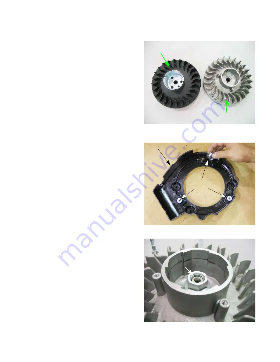
There are two types of flywheels available for the MTD 

engine. An aluminum flywheel and a 3-piece cast iron fly-
wheel. See Figure 7.22.

NOTE: 

The procedure for removing the flywheel is 

the same for both aluminum and cast iron 
flywheels.

To remove the flywheel:

1.

Remove the recoil assembly by following the steps 
described in Chapter 6: Starter.

2.

Lift the fan shroud off of the three studs that locate 
it. See Figure 7.23.

3.

Loosen the flywheel nut until it is a couple of threads 
past the end of the crank shaft using a 19mm 
wrench. See Figure 7.24.

Figure 7.22

Cast iron flywheel

Aluminum flywheel

Figure 7.23

Fan shroud

Shoulder 
bushings

Shoulder 
bushings fit 
over studs

Figure 7.24

A couple of threads past 

the end of the crank shaft 

Содержание 61 series

Страница 1: ...the product s Oper ators Manual supplied with the equipment No liability can be accepted for any inaccuracies or omission in this publication although care has been taken to make it as complete and a...

Страница 2: ......

Страница 3: ...ine 15 General torque specifications 15 Definitions 17 Chapter 2 Basic Troubleshooting Introduction 17 Steps to troubleshooting 17 Define the problem 17 Identify factors that could cause the problem 1...

Страница 4: ...Autochoke 52 Temperature compensating auto choke 53 Primer 54 Carburetors 55 Inspecting the carburetor 55 Disassembly and rebuilding the carburetor 56 Governor 61 Governor shaft 62 Governor cup and t...

Страница 5: ...96 Chapter 8 Exhaust To remove replace the conventional muffler 99 Catalytic converter muffler 101 Chapter 9 Cylinder Head Cylinder Head 103 Valves 106 Chapter 10 Crankshaft piston and Connecting Rod...

Страница 6: ...IV...

Страница 7: ...ent shall MTD be liable for poor text interpretation or poor execution of the procedures described in the text If the person using this manual is uncomfortable with any procedures they encounter they...

Страница 8: ...vents Respirator when working with chemical or solvents Appropriate tinted eye protection when cutting or welding Flame resistant headgear jacket chaps when cutting or welding WARNING WARNING CAUTION...

Страница 9: ...ation Whichever method is more appropriate will be used In many cases both will be used so that the manual is handy as a quick refer ence guide as well as a step by step procedure guide that does not...

Страница 10: ...d d e r h S r e p p i h C C D Mower long shaft M1 N Mower short shaft M0 E Mower short shaft M1 P Mower long shaft M0 F Mower short shaft no shroud Q Mower short shaft M0 G Garden Cart Side Discharge...

Страница 11: ...lways start with the model number Maintenance The recommended maintenance intervals listed in this manual are a guideline They are adjustable for local con ditions First oil change at 5 hours If equip...

Страница 12: ...ing failure no start occurs 3 Cleaning the spark plug NOTE MTD does not recommend cleaning spark plugs Use of a wire brush may leave metal deposits on the insulator that causes the spark plug to short...

Страница 13: ...ition it can be cleaned and reused The paper pleated filters can be shaken or lightly tapped to free the debris from the filter NOTE Never use compressed air on a paper air filter Compressed air will...

Страница 14: ...oil To simply look at synthetic oil and to compare it with Petroleum based oil there is very little difference However when you look at the two through a microscope it is easy to see the difference Sy...

Страница 15: ...ading it in to get the oil level reading See Figure 1 5 4 The oil level is determined by the lowest point on the dipstick that is completely covered with oil To check the oil with a 1 4 turn dip stick...

Страница 16: ...n the bottom of the dipstick tube A Place an approved oil drain pan next to the base of the dip stick B Remove the drain plug using a 1 4 extension See Figure 1 8 C Allow all of the oil to drain into...

Страница 17: ...pment should be no more than 30 days old Because it may already have been stored at the refinery or gas station for a week or more fuel should be purchased in small quantities and stored in safety app...

Страница 18: ...s were equipped with a fuel filter placed between the fuel tank and the car buretor See Figure 1 10 2 Currently the engines are equipped with a fuel filter installed in the fuel tank where the fuel li...

Страница 19: ...bolts that secure the valve cover using a 10mm wrench and remove the valve cover from the engine NOTE If care is used not to damage the valve cover gas ket it can be re used 5 Confirm that the piston...

Страница 20: ...e fulcrum nut with a 14mm wrench tighten the jam nut to a torque of 80 106 in lb 9 12 Nm using a 10mm wrench 11 Double check the clearance after tightening the jam nut to confirm that it did not shift...

Страница 21: ...N 5 9 1 6 9 3 3 m N 7 1 8 6 4 2 l a c i t i r c n o N n i s r e n e t s a F m u n i m u l A 4 1 M 2 1 M 0 1 M e z i s 8 M 6 M 5 M 4 M e z i s 3 4 7 2 6 1 s b l t f 3 9 8 3 2 2 1 1 s b l n i 8 4 e d a...

Страница 22: ...61 65 and 70 Series Vertical Shaft Engines 16...

Страница 23: ...to troubleshooting NOTE The steps and the order of the steps that follow are a suggested approach to troubleshooting the MTD engine The technician does not necessarily have to follow them as described...

Страница 24: ...cally accept that the customer is correct with their description of the problem Try to duplicate the problem 2b Check the general condition of the equipment visually I Cleanliness of the equipment wil...

Страница 25: ...n in the cylinder occurring at the right time II Compression enough pressure in the cylinder to convert combustion into kinetic motion It also needs sufficient sealing to generate the vacuum needed to...

Страница 26: ...governor setting or stuck governor a Check RPMs using a tachometer b RPMs should not droop under moderate to heavy loads V Low compression a Check valve lash b Check compression c Check leak down to...

Страница 27: ...il to exit the engine via any low resistance paths Piston rings Confirm with leak down test Smoke will be more pronounced under load Repair may not make economic sense Valve guides and intake valve st...

Страница 28: ...ope and see if the spark goes away at the same time the engine dies 4 Engine over speed A Continual over speed Binding or damaged external governor linkage or carburetor throttle Mis adjusted governor...

Страница 29: ...paired equipment confirming that the initial diagnosis was correct If it was wrong start the troubleshooting process over again NOTE Sometimes the engine will have multiple problems at the same time B...

Страница 30: ...mber with an external air source and will allow the technician to listen for air leaking at the valves piston rings and the head gasket NOTE These are general instructions Read and follow the instruct...

Страница 31: ...head gasket Air escaping from the exhaust Leaking exhaust valve Air escaping from the carburetor Leaking intake valve Gauge reading low Cylinder and piston rings are in good condition Gauge reading mo...

Страница 32: ...combustion chamber will result in an artificially high compression reading 1 Install a compression gauge in the spark plug hole 2 Confirm that the gauge is zeroed then pull the starter rope repeatedl...

Страница 33: ...air filter housing See Figure 2 3 To measure the crankcase pressure 1 Remove the dipstick 2 Attach a manometer to the dipstick tube 3 Start the engine 4 Read the measurement on the manometer See Fig u...

Страница 34: ...61 65 and 70 Series Vertical Shaft Engines 28...

Страница 35: ...61 65 and 70 series engines Paper filer with a thumb screw door Paper filter with a snap fit door Oval foam filter housing Round foam filter housing Paper filter with a thumb screw To access the air f...

Страница 36: ...control bracket using a 10mm wrench See Fig ure 3 4 3 Remove the two nuts that hold the air filter body to the carburetor mounting studs using a 10 mm wrench See Figure 3 4 4 Disconnect the crankcase...

Страница 37: ...steps in reverse order Foam air filter housing To remove the air filter housing 1 Remove the air filter by following the steps described in the previous section 2 Remove the screw that holds the air f...

Страница 38: ...mer out of the housing See Figure 3 10 NOTE Behind the filter housing is a steel plate with formed rubber gaskets vulcanized to each surface See Figure 3 11 NOTE Mark or note the orientation of the pl...

Страница 39: ...rs will col lapse the inner lining cutting off fuel flow 2b Double nut the studs for removal with a washer between the serrated faces of the nuts See Figure 3 12 2c After the second stud is removed th...

Страница 40: ...nhook the stabilizer spring that takes up the play between the governor arm the governor rod and the throttle arm on the carburetor NOTE The carburetors are not inter changeable from one engine model...

Страница 41: ...e gasket to the shape of the intake port The bowl vent channel in the insulator faces the carburetor with the exit toward the bottom There is a small hole in the insulator to carburetor gasket The hol...

Страница 42: ...61 65 and 70 Series Vertical Shaft Engines 36...

Страница 43: ...cted from the brass barb on the carburetor NOTE Replace the fuel line only with GREEN BARTM 700 series fuel line Inspect the fuel lines Are they cracked Are they clogged Are they brittle NOTE If the a...

Страница 44: ...some parts of the United States Fuel make up varies sea sonally and geographically Ethanol is the primary additive used to oxygenate fuel Ethanol in fuel creates a lot of problems for gasoline engines...

Страница 45: ...ilter is located in the fuel tank It can be removed and cleaned with a can of carb cleaner or replaced See Figure 4 4 NOTE On some early production engines an in line filter was used See Figure 4 5 Fi...

Страница 46: ...o pull a vacuum on the fuel tank with the gas cap in place 4 Attempt to pressurize the fuel tank with the gas cap in place NOTE The tank should not hold any pressure nor any vacuum Replace the cap if...

Страница 47: ...nbolt and remove the tank See Figure 4 8 5 Install by following the previous steps in reverse order Charcoal canister fuel tank To remove replace the fuel tank 1 Drain the fuel out of the fuel tank in...

Страница 48: ...Slanted neck tank To remove the fuel tank 1 Drain the fuel out of the fuel tank into an approved container 2 Disconnect the fuel line from the tank 3 Remove the recoil starter by following the proce d...

Страница 49: ...ree systems that can be used Charcoal canister fuel caps Charcoal canister system with the canister snapped into the tank Charcoal canister system with the canister snapped into the shroud NOTE All fu...

Страница 50: ...vapors 2 The vapors exit the fuel tank through the roll over valve vent NOTE The fuel cap used with the charcoal canister system is not vented If a vented cap is used the EVAP system will not work Se...

Страница 51: ...as follows 1 The gasoline evaporates letting off vapors 2 The vapors exit the fuel tank through a vacuum hose 3 The vapors are routed through the charcoal canister See Figure 4 20 4 The activated char...

Страница 52: ...nister or between the canister and the tank Engine runs rich Raw gasoline in the charcoal canister A blockage in the line between the char coal canister and the carburetor insulator plate Engine runs...

Страница 53: ...e Figure 4 22 3 Inspect the rubber grommet replace if damaged 4 With the grommet on the roll over valve install the roll over valve by pressing it into the opening in the tank See Figure 4 23 5 Instal...

Страница 54: ...following the steps described above 2 Connect a vacuum pump to the roll over valve 3 Hold the roll over valve in an inverted position 4 Apply a vacuum to the roll over valve See Figure 4 24 NOTE The r...

Страница 55: ...ter snapped into the shroud 1 Remove the recoil starter by following the procedures described in Chapter 6 Starters 2 Remove the fuel cap and tether by unscrewing them 3 Remove the fuel tank nut 4 Rem...

Страница 56: ...handle bar depending on the applica tion If the choke plate fails to close fully when the knob is pulled the mower will be difficult or impossible to start when cold NOTE The rod connecting the choke...

Страница 57: ...ake adjustments if the choke is not opening or closing fully 1 Remove the ignition module by following the steps described in Chapter 7 Ignition System 2 Loosen the screw that secures the air vane bra...

Страница 58: ...replace the air door 1 Remove the starter and blower housing by following the steps described in Chapter 6 Starters NOTE The air door is mounted to the underside of the blower housing See Figure 4 34...

Страница 59: ...ure compensator is installed on the muffler As the muffler heats up a bi metallic coil inside will expand The expand ing coil will rotate a lever towards the muffler pulling on a rod This rod will ove...

Страница 60: ...tors that use a primer are easily identified by the lack of a choke plate and the addition of a primer port See Figure 4 40 To remove replace the primer 1 Remove the air filter housing by following th...

Страница 61: ...d runs ok then that was the problem If it does not start move on to the car buretor Inspecting the carburetor 1 Remove the float bowl and check for dirt and or varnish 2 Inspect the needle valve and n...

Страница 62: ...4 43 3 Remove the bowl bolt using a 10mm wrench See Figure 4 44 NOTE From this point an assessment can be made about the viability of rebuilding the carbure tor If extensive corrosion is evident repla...

Страница 63: ...ect to wear it is suggested that technicians replace the valve and spring any time the carbure tor is disassembled for cleaning A square cross section gasket seals the bowl to the body of the carburet...

Страница 64: ...ation NOTE The main jet secures the emulsion tube in the central column of the carburetor See Figure 4 49 7 The throttle stop screw has a large pliable lip around the head of the screw That lip secure...

Страница 65: ...ut away view the passage by the metering port is visible See Figure 4 53 NOTE The pilot screw regulates how much of this pre mixed fuel air emulsion is allowed to enter the throat of the carburetor to...

Страница 66: ...able is 1 800 RPM 160 RPM set using throttle stop screw See Figure 4 55 For mower applications the idle speed is not normally critical because the operator is not provided with a throttle control 16 C...

Страница 67: ...n index mark to orient the shaft to the arm on installation remove the arm and go to step 3 1d Carefully slide the Governor arm off of the governor shaft 2 If the governor arm is being installed witho...

Страница 68: ...d steps 3 Remove the sump by following the steps described in Chapter 10 Disassembly 4 Remove the hair pin clip from the governor shaft See Figure 4 60 5 Slide the governor arm out of the engine block...

Страница 69: ...gine rpm and usually presents as an over speeding engine 11 Install the sump by following the steps described in Chapter 10 Disassembly 12 Rotate the governor shaft clockwise as far as it will go 13 P...

Страница 70: ...ngle screw models Inspect the plate for any deformity discard if any is found 4 Slide the gear shaft out of the gear and cup See Figure 4 66 5 Install by following the above steps in reverse order NOT...

Страница 71: ...le alternative but it does not extend service intervals NOTE MTD recommends the use of petroleum oil during the break in period to ensure the piston rings cor rectly break in Synthetic vs Petroleum ba...

Страница 72: ...e dipstick without threading it in to get the oil level reading See Figure 5 2 4 The oil level is determined by the lowest point on the dipstick that is completely covered with oil To check the oil wi...

Страница 73: ...p stick tube 1 Remove the dip stick 2 Remove the screw at the top of the dip stick tube See Figure 5 4 3 Pull the dip stick tube out of the engine block 4 Inspect the O rings on the dip stick and the...

Страница 74: ...forcing addi tional oil up to the cylinder head See Figure 5 7 The second oil passage runs along the bottom side of the cylinder This is the oil return passage As the name implies it allows the oil c...

Страница 75: ...ystem 2 Remove the two screws that hold the PCV chamber cover to the engine block using a 10mm wrench See Figure 5 9 3 The cover and gasket can be separated from the chamber See Figure 5 10 NOTE The d...

Страница 76: ...gure 5 12 6 Inspect the oil drain back port Make sure it will allow oil to drain back into the engine See Figure 5 13 NOTE Starting in the 2012 model year some engines where equipped with a new PCV br...

Страница 77: ...the breather port of the engine requiring the crankshaft to be removed to get it out 7 Reassemble the PCV 8 Tighten the cover bolts to a torque of 27 in lbs 3 Nm 9 Inspect the PCV tubing for cracks b...

Страница 78: ...61 65 and 70 Series Vertical Shaft Engines 72...

Страница 79: ...shroud to the engine See Figure 6 1 3 Remove the fuel cap 4 Lift the shroud off of the engine 5 Remove the engine cover and replace the fuel cap 6 Remove the three nuts that secure the recoil assem b...

Страница 80: ...el or starter cup NOTE If the flywheel or starter cup is replaced the complete starter should be replaced as well to prevent a repeat failure 2 If the engine has a steel starter cup remove it by remov...

Страница 81: ...tight to seat the knot firmly in the recess in the back of the pulley See Figure 6 6 6 Wind the spring completely Then relieve it minimum 1 full turn counting when the pulley knot aligns with the rop...

Страница 82: ...djusted there is room between the recoil housing and the pulley to wind on more tension See Figure 6 8 10 Install the starter and tighten the starter nuts to a torque of 80 106 in lbs 9 12 Nm Figure 6...

Страница 83: ...that are held in the disengaged position by two torsion springs 3 Inspect the pawls and torsion springs for wear and damage See Figure 6 10 4 Carefully lift the spring and pulley out of the recoil ho...

Страница 84: ...on springs and pawls so that the long arm of the spring reaches outside of the pawl and draws it toward the center of the assembly See Figure 6 12 NOTE The rolled end of the pawl fits in the recess in...

Страница 85: ...lace the starter relay 1 Unplug the starter harness See Figure 6 13 2 Remove the screw that secures the relay and dip stick tube using a 10mm wrench 3 Disconnect the two 12 AWG wires from the bottom o...

Страница 86: ...d lead from the middle tab of the blade brake switch See Figure 6 14 5 Connect a Digital MultiMeter DMM that is set to the Ohms scale to the two terminals on the bot tom of the relay See Figure 6 16 N...

Страница 87: ...y back wire on it See Fig ure 6 18 8 Reconnect the DMM with it still on the Ohms scale See Figure 6 19 NOTE The DMM should read less than 0 2 Ohms This relay has a burnt contact 9 If the test results...

Страница 88: ...emove the dip stick 4 Remove the two screws that secure the starter using a 10mm wrench See Figure 6 21 NOTE If replacing the starter make sure both dowel tubes are in the engine block See Figure 6 22...

Страница 89: ...Starters 83 Schematic 12V Charger connection 40A Fuse 12V Battery Motor Module Blade brake switch Starter relay Key switch...

Страница 90: ...61 65 and 70 Series Vertical Shaft Engines 84...

Страница 91: ...e full throttle position 4 Squeeze the safety bail if equipped and pull the starter rope If sparks can be seen in the spark tester the ignition system is working NOTE If there are sparks present in th...

Страница 92: ...4 NOTE If the reading is low the module is shorted to ground and may not produce a spark The wire will need to be traced back to the mod ule to find the short 7d Alternatively a jumper wire could be...

Страница 93: ...erly and the connection is good at the spade terminal but releasing the bail or turning off the switch fails to stop the engine then the problem lies within the module 9 The module 9a Normal performan...

Страница 94: ...e ignition should produce voltage approaching 12 000 See Figure 7 9 9e At pull over speed 600 RPM voltage should be at least 10 000V See Figure 7 10 NOTE Flash over voltage will vary with spark plug c...

Страница 95: ...laminations was observed to be in the 8K 9K range See Figure 7 12 NOTE There may be slight variation in specification due to production variation and other factors such as temperature Resistance figur...

Страница 96: ...d to confirm opposite polarity of the flywheel mag nets See Figure 7 13 11 Inspect the flywheel The flywheel is a frequently forgotten component of the ignition system It holds the magnets that induce...

Страница 97: ...amage may result Inspection of the spark plug Inspection of the spark plug can provide indications of the operating condition of the engine Light tan colored deposits on insulator and electrodes is no...

Страница 98: ...of the flywheel in relation to the crankshaft Proper timing is main tained by a steel key NOTE Regardless of which type of magneto is used the test procedures are the same Module removal 1 Unplug the...

Страница 99: ...er gauge between the mod ule and the flywheel See Figure 7 16 NOTE The air gap should be 0 012 0 020 0 3 0 5 mm 4 Rotate the flywheel so that the magnets align with the legs of the module while holdin...

Страница 100: ...e by 4a Squeeze the barbs together at the engine end of the cable housing and push it through the brake assembly 4b Unhook the Z fitting from the brake assembly See Figure 7 18 5 Disconnect the connec...

Страница 101: ...vot point and the bolt by the dip stick is in a slot See Figure 7 20 4 Use a spring clamp to hold the safety bail against the upper handle bar 5 Position the brake assembly so that the edge of the bra...

Страница 102: ...emove the flywheel 1 Remove the recoil assembly by following the steps described in Chapter 6 Starter 2 Lift the fan shroud off of the three studs that locate it See Figure 7 23 3 Loosen the flywheel...

Страница 103: ...e Figure 7 27 NOTE If the key is damaged it must be replaced If there is damage to the crankshaft key way the engine must be short blocked because crankshafts are not available as a service part 6 On...

Страница 104: ...el nut to a torque of 47 52 ft lbs 64 70 Nm NOTE If the engine has a cast iron flywheel install a starter cup by placing the starter cup on the flywheel Allow the protrusion on the bot tom of the star...

Страница 105: ...lers a standard muffler covered here or a catalytic converter muf fler that will be covered later in this chapter To remove replace the conventional muffler 1 Remove the muffler cover that is secured...

Страница 106: ...ust gasket is made of a graphite material It will stick to the sealing surfaces when pressure is applied tearing when pressure is relieved The gasket can only be used one time 3 Clean the cylinder hea...

Страница 107: ...converter so that it can complete its chemical reaction inside the muffler NOTE Stoichiometric point is defined as the point where the mass ratio of fuel to air is chemically balanced For gasoline th...

Страница 108: ...Burned clean using a butane or propane torch 3 Install the inlet screen cover and tighten the screws to a torque of 44 in lbs 5 Nm 4 Clean the gasket material from the air injector and the muffler See...

Страница 109: ...iod of time The oil will seep into the breather chamber NOTE It is not absolutely essential to remove the fan shroud but taking the engine cover off if equipped will ease access to some components 1 D...

Страница 110: ...their original locations on engine with substantial 100 hours operat ing time 7 Remove the muffler by following the steps described in Chapter 8 Exhaust 8 Double nut and remove the exhaust studs using...

Страница 111: ...ad bolts are loosened 14 Position the cylinder head on the engine block 15 Install the 4 head bolts and tighten them to a step torque of 212 in lb 24 Nm in an alternating diagonal pattern See Figure 9...

Страница 112: ...lve repairs are to be accomplished by replacing the cyl inder head 1 Remove the cylinder head by following the steps described earlier in this chapter 2 Remove the rocker arms by 2a Remove the jam nut...

Страница 113: ...6 mm 9 Install the valves in the cylinder head by following steps 2 5 in reverse order 10 Test the valves for leaks by 10a Place the cylinder head on a couple of wood blocks with the valves facing up...

Страница 114: ...61 65 and 70 Series Vertical Shaft Engines 108...

Страница 115: ...pter 4 Fuel system and Governor 3 Remove the starter by following the steps described in Chapter 6 Starter systems 4 Remove the flywheel and ignition module by following the steps described in Chapter...

Страница 116: ...ure 10 2 NOTE Align the timing marks to allow easier removal of the cam shaft and to help protect the compression relief from damage NOTE Early production of the 1P70 series engines had a steel cam sh...

Страница 117: ...he proper orientation NOTE Rotating the crank shaft after the connecting rod bolts are removed will help to separate the connecting rod from the cap See Figure 10 6 14 Push the piston out of the cylin...

Страница 118: ...5 Check the crank shaft for straightness by measuring the run out The crank shaft run out can be check by 5a Place the crank shaft on a pair of matched V blocks or in the engine block with the sump i...

Страница 119: ...pter See Fig ure 10 11 4 Repeat steps 3 and 4 on the other rings NOTE Piston rings are not available as service parts If any of the end gaps are out of spec the engine must be short blocked 5 Install...

Страница 120: ...ing rod and compare the measurements to those listed in the chart at the end of this chapter See Figure 10 15 NOTE Take two measurements 90 degrees apart This will check the out of roundness of the co...

Страница 121: ...Compare the measurements to those that are listed in the chart at the end of the chapter 3 Inspect the cylinder cross hatch See Figure 10 18 NOTE The X65 series engine has a smooth aluminum bore no cr...

Страница 122: ...OTE Do not de glaze an X65 series engine cylin der If the cylinder needs to be de glazed replace the cylinder block Bearings There are two bearings to inspect a plain bearing in the sump and a ball be...

Страница 123: ...ankshaft into the cylinder block bearing NOTE Pre lube the crank shaft with clean 10W 30 motor oil or engine assembly lube NOTE Use an old piece of microfiche or a seal protector to protect the oil se...

Страница 124: ...e lube the connecting rod with clean 10W 30 motor oil or engine assembly lube 4f Install the connecting rod cap Apply a small amount of releasable thread locking compound such as Loctite 242 blue to t...

Страница 125: ...marks See Figure 10 28 7 If removed install the governor arm by following the steps described in Chapter 4 Fuel systems and Gov ernor 8 If removed install the oil return deflector See Figure 10 29 9...

Страница 126: ...ribed in Chapter 9 Cylinder head 12 Install the muffler by following the steps described in Chapter 8 Exhaust 13 Install the fuel tank by following the steps described in Chapter 4 Fuel systems and Go...

Страница 127: ...und P61 0 000 0 000 0 000 0 005 0 000 0 005 P65 0 000 0 000 0 000 0 005 0 000 0 005 X65 0 000 0 000 0 000 0 005 0 000 0 005 P70 0 000 0 000 0 000 0 005 0 000 0 005 Cylinder taper P61 0 000 0 000 0 000...

Страница 128: ...020 1 026 26 060 P70 1 182 30 015 1 182 30 025 1 184 30 061 Connecting rod ID piston side P61 0 520 13 204 0 520 13 212 0 521 13 232 P65 0 520 13 204 0 520 13 212 0 521 13 232 X65 0 512 13 004 0 512 1...

Страница 129: ...551 13 984 0 547 13 898 P65 0 550 13 966 0 551 13 984 0 547 13 898 X65 0 550 13 966 0 551 13 984 0 547 13 898 P70 0 550 13 966 0 551 13 984 0 547 13 898 Cam shaft OD sump side P61 0 550 13 966 0 551...

Страница 130: ...511 1 091 27 711 1 081 27 465 P65 1 085 27 561 1 089 27 661 1 079 27 416 X65 1 085 27 561 1 089 27 661 1 079 27 416 P70 1 092 27 740 1 096 27 840 1 086 27 593 Compression ring end gap P61 0 006 0 150...

Страница 131: ...0 200 P65 0 006 0 150 0 008 0 200 X65 0 006 0 150 0 008 0 200 P70 0 005 0 130 0 007 0 170 Spark plug gap P61 0 024 0 600 0 031 0 800 P65 0 024 0 600 0 031 0 800 X65 0 024 0 600 0 031 0 800 P70 0 024...

Страница 132: ...lbs 12 14 Nm Flywheel nut 48 52 ft lbs 64 70 Nm 48 52 ft lbs 64 70 Nm 48 52 ft lbs 64 70 Nm 48 52 ft lbs 64 70 Nm Head bolt 20 22ftlbsstep 28 30 Nm 20 22ftlbsstep 28 30 Nm 20 22ftlbsstep 28 30 Nm 20 2...

Страница 133: ...asive Ingestion is when hard particles are introduced into the engine Particles can be introduced into the engine by leaks in the air intake system through a dirty oil fill plug or by particles of met...

Страница 134: ...ottom will show this Other sources of abrasives that get into the engine includes carbon that builds up on the top side of the piston metal shavings from the wear of engine parts or dirt enter ing thr...

Страница 135: ...are trapped in the oil will cause the lower portion of the combustion chamber to wear ing more than the upper portion NOTE Wear of only one bearing surface on a new engine could be a sign of a manufa...

Страница 136: ...s It forms a cushion between moving parts protecting them from contact with each other When an engine is properly lubricated all of the moving parts glide on a thin film of oil If that film breaks dow...

Страница 137: ...of the failure Larger size abrasive particles can render the lubricants ineffective leading to an engine failure An overheated engine can cause the oil to break down leading to a failure In an engine...

Страница 138: ...mage to it Usually the connecting rod will be in several pieces after it breaks making it hard to find where the first failure was 2 All engines create a certain amount of vibration when they are oper...

Страница 139: ...like cylinder heads the hottest part of the engine As they try to expand they fight against the head bolts The head bolts will not move to allow the expansion so the head warps to allow the expan sion...

Страница 140: ...n of the fuel spontaneously igniting the combustion chamber prior to the spark plug firing In this state the flame front from the detonation will start to travel through the combustion chamber and a s...

Страница 141: ......

Страница 142: ...MTD Products Inc Product Training and Education Department FORM NUMBER 769 03354 02 12 2013...

Отзывы: