


2-12
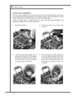
Hardware Setup
▍
MS-96D2
Hardware Setup
▍
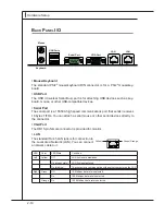
MS-96D2
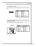
Important
Note that the pins of VCC and GND must be connected correctly to avoid pos-
sible damage.
Front USB Connector: JUSB1 / JUSB2 / JUSB3 / JUSB4
Ths connector, complant wth Intel® I/O Connectvty Desgn Gude, s deal for
connectng hgh-speed USB nterface perpherals such as USB HDD, dgtal cam-
eras, MP3 players, prnters, modems and the lke.
ID Connector: JID1
Ths connector s used to connect the optonal ID button.
1
PIN
SIGNAL PIN
SIGNAL
1
3
5
7
9
VCC
USB0-
USB0+
GND
KEY
2
4
6
8
10
VCC
USB1-
USB1+
GND
NC
10
9
2
1
USB 2�0 Bracket
(Optonal)
PIN
SIGNAL
1
2
ID_BTN_N
GND
Содержание MS-96D2
Страница 1: ...MS 96D2 v1 X Server Board...
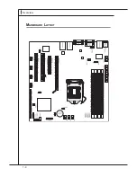
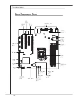
Страница 12: ...1 4 Overview Overview Mainboard Layout...
Страница 14: ......
Страница 32: ......
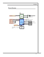
Страница 45: ...MS 96D2 3 13 MS 96D2 Chipset North Bridge...


