background image

Hardware Setup

MS-96D2

2-7

Hardware Setup

MS-96D2

M

eMory

These DIMM slots are intended for memory modules.

DDR3

240-pin, 1.5V

48x2=96 pin 

72x2=144  pin

Single-Channel Mode Population Rule


1


 DIMM2


 DIMM4


 DIMM1


 DIMM3


2


 DIMM2


 DIMM4


 DIMM1


 DIMM3

Dual-Channel Mode Population Rule

In Dual-Channel mode, the memory modules can transmit and receive data with 

two data bus lines simultaneously. Enabling Dual-Channel mode can enhance 

the system performance. The following illustrations explain the population rules 

for Dual-Channel mode.


1


 DIMM2


 DIMM4


 DIMM1


 DIMM3


2


 DIMM2


 DIMM4


 DIMM1


 DIMM3

Installed
Empty


Содержание MS-96D2

Страница 1: ...MS 96D2 v1 X Server Board...

Страница 2: ...emarks of Microsoft Corporation AMI is registered trademark of Advanced Micro Devices Inc Award is a registered trademark of Phoenix Technologies Ltd Sound Blaster is registered trademark of Creative...

Страница 3: ...nings on the equipment should be noted Never pour any liquid into the opening that could damage or cause electrical shock If any of the following situations arises get the equipment checked by ser vic...

Страница 4: ...t the interference by one or more of the measures listed below Reorient or relocate the receiving antenna Increase the separation between the equipment and receiver Connect the equipment into an outle...

Страница 5: ...r als kommunale Abf lle entsorgt werden MSI hat europaweit verschiedene Sammel und Recyclingunternehmen beauftragt die in die Europ ische Union in Verkehr gebrachten Produkte am Ende seines Leb enszyk...

Страница 6: ...de producten die de merknaam MSI dragen en verkocht zijn in de EU Deze goederen kunnen geretourneerd wor den op lokale inzamelingspunten SRPSKI Da bi za titili prirodnu sredinu i kao preduze e koje vo...

Страница 7: ...h sb rn ch MAGYAR Annak rdek ben hogy k rnyezet nket megv dj k illetve k rnyezetv d k nt fel l pve az MSI eml kezteti nt hogy Az Eur pai Uni EU 2005 augusztus 13 n hat lyba l p az elektromos s elek tr...

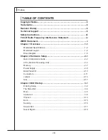
Страница 8: ...verview 1 1 Mainboard Specifications 1 2 Mainboard Layout 1 4 Block Diagram 1 5 Chapter 2 Hardware Setup 2 1 Quick Components Guide 2 2 CPU Central Processing Unit 2 3 Memory 2 7 Power Supply 2 9 Back...

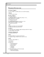
Страница 9: ...dates the latest Intel Clarkdale Lynnfield processor in LGA1156 package and supports up to 4 DDR3 800 for rigistered memory 1066 1333 DIMM slots to provide the maximum of 16GB unbuffered 32GB rigister...

Страница 10: ...field Support Dual Channels LAN Gigabit Fast Ethernet by Intel 82578DM Gigabit Fast Ethernet by Intel 82574L Graphics Integrated by Intel Ibexpeak chipset and Aspeed AST1100 chipset Onboard 8MB Video...

Страница 11: ...Clear CMOS jumper 1 Chassis Intrusion connector 1 TPM Module connector 1 Front Panel ID pinheader 1 Recovery jumper Slot 1 PCI Express x16 slot 1 PCI Express x8 slot with x4 signal 2 PCI slots suppor...

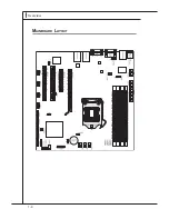
Страница 12: ...1 4 Overview Overview Mainboard Layout...

Страница 13: ...actor Micro ATX 6 layers 6x USB2 0 2x Rear 4x Internal SIO SMSC SCH5617 LPC SPI Flash SPI Hankswilk 82578 PCI Mechanical x8 Intel FDI DUWZHOO PCIe x1 1 KLS 36 06 20 3RUW 5HDU SLQ KHDGHU 5 CPU Lynnfiel...

Страница 14: ......

Страница 15: ...ion be careful in holding the components and follow the installation procedures For some components if you install in the wrong orientation the components will not work properly Use a grounded wrist s...

Страница 16: ...9 JPWR2 p 2 9 JTPM1 p 2 15 JCOM2 p 2 11 Back Panel I O p 2 10 SYS_FAN3 p 2 11 CPU_FAN1 p 2 11 SYS_FAN1 p 2 11 SYS_FAN2 p 2 11 J_CMOS1 p 2 16 JUSB1 4 p 2 12 SATA0 5 p 2 13 JCASE1 p 2 14 JFP1 p 2 15 JSM...

Страница 17: ...to enhance heat dissipation Replacing the CPU While replacing the CPU always turn off the ATX power supply or unplug the power supply s power cord from the grounded outlet first to ensure the safety o...

Страница 18: ...CPU cooler correctly Wrong installation will cause the damage of your CPU mainboard Open the load level 1 Lift the load lever up to fully open position 2 The CPU socket has a plastic cap on it to pro...

Страница 19: ...load lever while pressing down lightly onto the load plate 6 Secure the lever near the hook end under the retention tab 7 Make sure the four hooks are in porper position before you install the cooler...

Страница 20: ...arance of your mainboard may vary depending on the model you purchase Please refer to the documentation in the CPU fan package for more details about the CPU fan installation Align the holes on the ma...

Страница 21: ...3 2 DIMM2 DIMM4 DIMM1 DIMM3 Dual Channel Mode Population Rule In Dual Channel mode the memory modules can transmit and receive data with two data bus lines simultaneously Enabling Dual Channel mode ca...

Страница 22: ...Insert the memory module vertically into the DIMM slot Then push it in until the golden finger on the memory module is deeply inserted in the DIMM slot The plastic clip at each side of the DIMM slot...

Страница 23: ...ned Then push down the power supply firmly into the connector You may use the 20 pin ATX power supply as you like If you d like to use the 20 pin ATX power supply please plug your power supply along w...

Страница 24: ...rial devices directly to the connector VGA Port The DB15 pin female connector is provided for monitor LAN The standard RJ 45 LAN jack is for connection to the Local Area Network LAN You can connect a...

Страница 25: ...ensor to take ad vantage of the CPU fan control Important Please refer to the recommended CPU fans at processor s official website or consult the vendors for proper CPU cooling fan Serial Port Connect...

Страница 26: ...with Intel I O Connectivity Design Guide is ideal for connecting high speed USB interface peripherals such as USB HDD digital cam eras MP3 players printers modems and the like ID Connector JID1 This...

Страница 27: ...onnector is a high speed Serial ATA interface port Each connector can connect to one Serial ATA device Important Please do not fold the Serial ATA cable into 90 degree angle Otherwise data loss may oc...

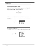
Страница 28: ...status and show a warning message on the screen To clear the warn ing you must enter the BIOS utility and clear the record I2C Bus Connector JSMBUS1 This connector known as I2C is for users to connec...

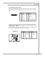
Страница 29: ...nects to an optional TPM Trusted Platform Module Please refer to the TPM security platform manual for more details PIN SIGNAL PIN SIGNAL 1 3 5 7 9 11 13 15 HDD HDD GND SYS_RST_N NC FP_ID_LED_N P3V3_AU...

Страница 30: ...an clear CMOS by shorting 2 3 pin while the system is off Then return to 1 2 pin position Avoid clearing the CMOS while the system is on it will damage the mainboard VGA Control Jumper J_VGA1 This jum...

Страница 31: ...power supply first Meanwhile read the documentation for the expansion card to config ure any necessary hardware or software settings for the expansion card such as jumpers switches or BIOS configurati...

Страница 32: ......

Страница 33: ...ws you to configure the system for op timum use You may need to run the Setup program when An error message appears on the screen during the system booting up and requests you to run SETUP You want to...

Страница 34: ...e items under each BIOS category described in this chapter are under continuous update for better system performance Therefore the description may be slightly different from the latest BIOS and should...

Страница 35: ...r symbol as shown in the right view appears to the left of certain fields that means a sub menu can be launched from this field A sub menu contains additional options for a field parameter You can use...

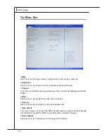
Страница 36: ...the advanced features of the onboard Northbridge and South bridge Boot Use this menu to specify the priority of boot devices Security Use this menu to set supervisor and user passwords Save Exit This...

Страница 37: ...nd hardware specifications of your system Read only System Language This setting controls the system language System Date This setting allows you to set the system date The date format is Day Month Da...

Страница 38: ...3 6 BIOS Setup BIOS Setup Advanced Launch PXE OpROM Launch Storage OpROM Use these settings to launch the PXE option ROM storage option ROM ACPI Settings...

Страница 39: ...ock alarm awakens the system from suspend mode Trusted Computing TPM Support This setting controls the Trusted Platform Module TPM designed by the Trusted Computing Group TCG TPMs are special purpose...

Страница 40: ...this item if your operating system doesn t support HT Function or unreliability and instability may occur Intel Virtualization Technology Virtualization enhanced by Intel Virtualization Technology wil...

Страница 41: ...ny of the bottlenecks associated with HDD latency By enabling the major ity of application workload to be written and read from a system cache instead of the HDD Turbo Memory will offer users signific...

Страница 42: ...3 10 BIOS Setup BIOS Setup Super IO Configuration Serial Port 0 Configuration Serial Port 1 Configuration Serial Port This setting enables disables the specified serial port...

Страница 43: ...t systems that do not have a monitor and keyboard attached This setting enables disables the operation of console re direction When set to Enabled BIOS redirects and sends all contents that should be...

Страница 44: ...e transfer rate bits per second data bits parity stop bits of Console Redirection Flow Control Flow control is the process of managing the rate of data transmission be tween two nodes It s the process...

Страница 45: ...MS 96D2 3 13 MS 96D2 Chipset North Bridge...

Страница 46: ...reboot after a power failure or interrupt occurs Available settings are Power Off Leaves the computer in the power off state Power On Leaves the computer in the power on state Last State Restores the...

Страница 47: ...turn on the Num Lock key when the system is powered on Setting to Off will allow users to use the arrow keys on the numeric keypad Boot Option Priorities The items allow you to set the sequence of boo...

Страница 48: ...sers will be prompted for Administrator password only when they enter BIOS Setup User Password User Password controls access to the system at boot and access to the BIOS Setup utility Users will be pr...

Страница 49: ...hanges to CMOS and reset the system Discard Changes and Reset Abandon all changes and reset the system Save Changes Save all changes and continue with the Setup Utility Discard Changes Abandon all cha...

Страница 50: ...3 18 BIOS Setup BIOS Setup Server Mgmt 3pin 4pin Fan This setting specifies the number of fan connector pins BMC Network Configuration...

Страница 51: ...MS 96D2 3 19 MS 96D2 Configuration Source This setting selects whether to configure LAN channel parameters statically or dynamically DHCP Do Nothing will not modify any BMC network param eters in BIOS...

Отзывы: