


Manual ERS (Energy Recovery System)
MSF-Vathauer Polska Sp. z.o.o ul. Staszica 37 PL-64-600 Oborniki
Tel: 0048 503972873 E-mail
www.msf-technik.pl
Page 7 of 23
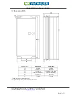
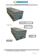
2. Assembly and Installation
2.1. Installation
The device requires adequate ventilation.
The hot air has to be dissipated above the ERS!
2.2. Cabling directives of superior controls
The ERS is developed for the operation in industrial environments where high values of
electromagnetic interferences are expected. In general, a professional installation ensures a risk less
and error-free operation. If limits are required that exceed the EMC directive limits, the following
directives are recommended.
1. Please make sure that all devices in the control cabinet are connected together at a shared
grounding point or rail with short cores and great diameter are properly grounded. It is
especially important that every control device connected to the frequency inverter and the
ERS (e.g. automation devices) is connected via a short core with high diameter at the same
grounding point as well as the frequency inverter and the ERS itself.
2. The PE conductor
of the motor controlled by the frequency inverter should preferably directly
connected to the ground connection, connected with the heat sink together with the PE of the
power supply of the concerning inverter. The existence of a central grounding rail within the
control cabinet and the connection of alll PE conductors to this rail normally guarantee an
error-free operation.
3. As far as possible screened cables for the control should be used. The cable ends have to be
terminated carefully and ensure that the cores are not unscreened over long distances. The
screen of analogue set point cables should only be grounded at the frequency Inverter single-
sided. Not used cores of the control cable should be grounded.
4. The control cables have to be laid in the most possible distance from the load cable using
separated cable trenches etc. Cable crosses should possibly get an angle of 90°.
5. Make sure that contactors and relays in the control cabinets are suppressed either by RC
connection or varistors in case of AC contactors or by „ freewheeling diodes “at DC
contactors, wherein the interference suppression bust be attached to the coils. The
suppression is especially important if the contactors are controlled by the relay in the
frequency Inverter (optional).
6. Use screened cores for the load connections and ground the screening at both ends, if
possible directly at the PE output of the Inverter.
7. If the drive should run within an environment sensible to electro-magnetic interference, the
usage of interference filters is recommended to reduce the grid-bound and radiated
interferences of the Inverter. In this case install the filter as near as possible to the inverter and
take care and be well grounded.
8. Choose the lowest possible switching frequency. This minimizes the intensity of the electro-
magnetic interference created by the frequency Inverter.
During the installation of the ERS at the frequency inverter the safety regulations must not be
violated!!! Instructions of the Inverter manufacturer have to be observed!!!!


