background image


Manual ERS (Energy Recovery System) 


MSF-Vathauer Polska Sp. z.o.o     ul. Staszica 37    PL-64-600 Oborniki 
Tel: 0048 503972873   E-mail 

[email protected]

   www.msf-technik.pl 


Page 18 of 23 

6. Commissioning

 instructions


For quick setup and trouble-free operation of the ERS the following procedure is recommended when 
commissioning.  

 
1. If 

it is in an existing plant and a brake chopper is used, it is recommended that the voltage across 

the resistor is looked at with a suitable instrument (Multimeter, oscilloscope, etc.).  
Based on the maximum operating voltage you can make the default setting of thresholds (sec. 3.4.) at 
the ERS. Alternatively, the switching thresholds of the brake chopper can be taken from the technical 
documentation or requested of the device manufacturer of the frequency inverter or servo drive.   

 
2. Switch the controller without voltage  
 
3. Connect the ERS to the DC link terminals of the inverter or the servo controller (e.g. sec. 4.3. / 4.4.). 
To comply with EMC, it is advisable to use a shielded cable and the shielding on both sides. 
  
!!! IMPORTANT: Please note the polarity of the DC link voltage. It is NOT a polarity protection in 
the ERS integrated 
 
4. Connect the ERS with the 3-phase supply network 
 
!!! IMPORTANT: The operation of the ERS is only possible on a CLOCKWISE ROTATING 
FIELD!!!!!!  
 
5. 

If necessary, connect the inputs / outputs of the ERS with your application.


!!! RECOMMENDATION: During the initial commissioning it is recommended that the enable 
input (sec. 5.1.) when switching on the controller is not set to!!!!!!  
 
6. Switch on the controller 
 
7. 

After a moment, a visual indicator appears in the ERS (sec. 8.) 


8. If network synchronization was successful and no other error is displayed, "Enable" can be set.  
This is indicated by visual display (sec.8.) 
  
9. Subsequently, a test run can be performed 
 
!!! INFO: The feedback operation of the ERS is visually displayed (sec. 8.)!!! 
!!!TIP: Set the switching thresholds so that the brake chopper is used as little as possible or 
not at all in normal mode!!! 
 
!!! IMPORTANT: Please note that the feedback mode is possible only with existing 3-phase 
voltage. If during the regenerative operation or shortly before it comes to a fault, it is 
recommended to provide a braking resistor for emergency braking!!! 
 

Содержание ERS

Страница 1: ...overy System MSF Vathauer Polska Sp z o o ul Staszica 37 PL 64 600 Oborniki Tel 0048 503972873 E mail info msf technik pl www msf technik pl Page 1 of 23 Manual Energy Recovery System Version 23 2018 Rev 1 5 Date 06 06 2018 ...

Страница 2: ... months in single shift after delivery on all electronic devices covering design material or faulty workmanship MSF Vathauer Antriebstechnik reserves the right to change the contents of this operation manual and the product specifications contained therein without prior notice The copyright of this documentation is reserved by MSF Vathauerer Antriebstechnik GmbH Co KG Attention Read this manual ca...

Страница 3: ...ing signal and control cables 8 2 7 Coupling into motor cables 8 3 Technical features 9 3 1 Special features 9 3 3 Sample Application 10 3 4 Switching thresholds 11 3 5 Adjustment of the switching threshold 11 4 Connection Diagrams 12 4 1 Connection diagram front side 12 4 2 Connection diagram rear side 12 4 3 Connection example FU with external brake chopper 13 4 4 Connection example FU with ERS ...

Страница 4: ...tended Use The ERS is a component which is intended for installation only in machines in commercial installations in conjunction with a frequency inverter or a servo controller The commissioning of the ERS frequency inverter or ERS Servo controller constellation is prohibited until it is determined that the machine in which the device is installed complies with the provisions of EU Directive 2006 ...

Страница 5: ...round wire connection More detailed information is to be found in the documentation Compliance with the limits for the plant according to the EMC juridical directive is in responsibility of the manufacturer of the plant Information about the EMC compatible installation like screening grounding alignment of filters and lying of cables are to be found in the documentation of the other components 1 6...

Страница 6: ...tput clamps or blocked drive the voltage circuit clamps motor clamps and clamps for the brake resistance may conduct dangerous voltage A motor standstill is not identical with a galvanic disconnection from the mains voltage Attention The ERS may after the mains are switched on depending on the settings start automatically the regenerative mode Attention Danger to Life The power supply conducts vol...

Страница 7: ... an error free operation 3 As far as possible screened cables for the control should be used The cable ends have to be terminated carefully and ensure that the cores are not unscreened over long distances The screen of analogue set point cables should only be grounded at the frequency Inverter single sided Not used cores of the control cable should be grounded 4 The control cables have to be laid ...

Страница 8: ...erted into the lead bound transfer way between the source of interference and the interference suppressor which is to reduce lead bound transmissions and to increase the noise immunity Additional external filter may have a negative effect on the noise emission 2 6 Screening signal and control cables Screening is used for decoupling fields between two spatially separate areas i e is also used to de...

Страница 9: ...o the intermediate circuit of the inverter or the servo controller The voltage is monitored and upon reaching the respective threshold the feedback mode is automatically activated The thresholds are adjustable via a selector switch inside the unit The ERS operates on 3ph AC voltage network and synchronizes automatically at the connection There is no programming required The device is immediately r...

Страница 10: ...tinuous analogously measured and fed to the control algorithm Once the DC link voltage has reached the threshold Sec 3 4 begins the ERS with the feedback of energy into the grid Important requirements for the operation of the ERS For the operation of the ERS is an 3phase Power grid necessary The frequency inverter or the servo controller must establish a relationship to the power supply via an unc...

Страница 11: ...e refer to the respective manufacturer for the thresholds of the respective frequency inverter or servo drive Switch Turn On Off threshold Feedback activated deactivated 0 540 V 1 560 V 2 580 V 3 600 V 4 620 V 5 640 V 6 660 V 7 680 V 8 700 V 9 720 V A 740 V B 760 V C 780 V D reserved E reserved F reserved MSF factory setting 3 5 Adjustment of the switching threshold A selector switch is provided i...

Страница 12: ...em MSF Vathauer Polska Sp z o o ul Staszica 37 PL 64 600 Oborniki Tel 0048 503972873 E mail info msf technik pl www msf technik pl Page 12 of 23 4 Connection Diagrams 4 1 Connection diagram front side 4 2 Connection diagram rear side ...

Страница 13: ...em MSF Vathauer Polska Sp z o o ul Staszica 37 PL 64 600 Oborniki Tel 0048 503972873 E mail info msf technik pl www msf technik pl Page 13 of 23 4 3 Connection example FU with external brake chopper 4 4 Connection example FU with ERS ...

Страница 14: ...37 PL 64 600 Oborniki Tel 0048 503972873 E mail info msf technik pl www msf technik pl Page 14 of 23 4 5 Connection example FU interconnection with an ERS FU must be suitable for intermediate circuit connection 4 6 Connection example FU interconnecting circuit with several ERS ...

Страница 15: ...ery System MSF Vathauer Polska Sp z o o ul Staszica 37 PL 64 600 Oborniki Tel 0048 503972873 E mail info msf technik pl www msf technik pl Page 15 of 23 FU must be suitable for intermediate circuit connection 5 In and Outputs ...

Страница 16: ...al 4 The reference potential for the digital output is the terminal 6 DGND As supply voltage an external power source or the on to terminal 1 24Vdc provided voltage can be used The Open Emitter output is for maximum 30V 40mA load As external power source may be max 30V used 5 3 Digital Output 2 DOUT2 The ERS has a digital output 2 sect 4 2 This output shows the status of the feedback Upon reaching...

Страница 17: ...res a three phase supply network If this network fails or one of the three phases is missing then the devise goes into malfunction and can not return any regenerative energy In this case there is the possibility to use the built in emergency resistor However this assumes that of the frequency inverter or servo controller in use has a built in brake chopper connection and that the integrated resist...

Страница 18: ...able and the shielding on both sides IMPORTANT Please note the polarity of the DC link voltage It is NOT a polarity protection in the ERS integrated 4 Connect the ERS with the 3 phase supply network IMPORTANT The operation of the ERS is only possible on a CLOCKWISE ROTATING FIELD 5 If necessary connect the inputs outputs of the ERS with your application RECOMMENDATION During the initial commission...

Страница 19: ...350 480V Mains filter Internal Output Mains side Mains frequency 50 60 Hz Regenerative power 2 9A ca 5kW ED35 ca 2kW ED100 Protection class IP 20 optional IP 54 General Data Ambient temperature 0 40 C Humidity 20 90 rel Not dewing Dimensions IP20 312 x 112 x 92 mm IP54 434 x 112 x 92 mm Weight 2 1kg The feedback operation is only possible Sec 3 2 if the DC link voltage is above the amplitude value...

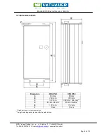
Страница 20: ...72873 E mail info msf technik pl www msf technik pl Page 20 of 23 7 2 Measurement ERS Dimension ERS IP20 ERS IP54 A 65 mm 65 mm B 290 mm 370 mm C 312 mm 392 mm 434 mm D 90 mm 92mm 90 mm 92mm E 112 mm 112 mm F 5 mm 5 mm Height incl cover for the selector switch Length including cable glands at the top and bottom ...

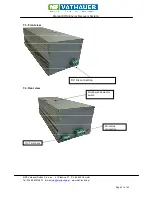
Страница 21: ...hauer Polska Sp z o o ul Staszica 37 PL 64 600 Oborniki Tel 0048 503972873 E mail info msf technik pl www msf technik pl Page 21 of 23 7 3 Front view 7 4 Rear view AC mains connection Window and selector switch IO Terminals DC link connection ...

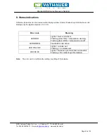
Страница 22: ...w Status of network synchronization is also displayed by the digital output sec 5 2 5 3 Error code Meaning LED RED Lights fault overcurrent Flashing slow 1Hz temperature warning Flashing fast 0 5Hz temperature cut off LED GREEN Feedback mode active LED YELLOW Lights release set Flashing no release set LED BLUE Lights Network synchronization successful Flashing No network synchronization Note The e...

Страница 23: ...Manual ERS Energy Recovery System MSF Vathauer Polska Sp z o o ul Staszica 37 PL 64 600 Oborniki Tel 0048 503972873 E mail info msf technik pl www msf technik pl Page 23 of 23 Notes ...

Отзывы: