Operation
IMPORTANT
: ensure all electrical connections are isolated before commencing any work on the unit.
During installation, adjust the “Extension Limit” to the maximum number of hours the extension period can
to be allowed to run for (recommended: 4 hours).
Operation Modes
Standby:
Power-saving dim LED displays showing “0” on all digits.
Setting Up: Bright LED displays with the currently selected digit blinking.
Running:
Bright LED displays with the “Running” LED blinking.
“On” LED illuminates when the extension is active.
“Increase” Pushbutton
Press:
Increments the blinking digit by 1 unit.
Hold:
Increments the blinking digit automatically while held down.
“Select/Start/Stop” Pushbutton
Press:
Selects the next digit to adjust (disabled when running).
Hold:
Starts or stops the extension.
Typical Example
16 hours delay with a 4 hour extension period:
a. From Standby mode Press “Select” to select the first digit of “Delay”.
b. Press “Increase” to increment the first digit to “1”.
c. Press “Select” to select the second digit of “Delay”
d. Hold “Increase” until the second digit increments to “6”.
e. Press “Select” to select the “Extension” digit.
f. Hold “Increase” until the digit shows “4”.
g. Hold “Start” to start the extension running.
The E313 will count down 16 hours before enabling the relay output for 4 hours.
Additional Operating Guidelines
a. The extension may be cancelled at any time by holding down the “Stop” button.
Technical Specification
Power supply:
85 - 265V AC, 50 - 60Hz (live/neutral/earth)
Output switch rating:
10A @ 250V AC (resistive)
Output switch type:
Changeover relay (volt-free)
Operating temperature:
-10°C to +40°C
Suitable for:
22mm (or deeper) single-gang UK pattress box
Guarantee:
5 Years
Weight:
0.3kg
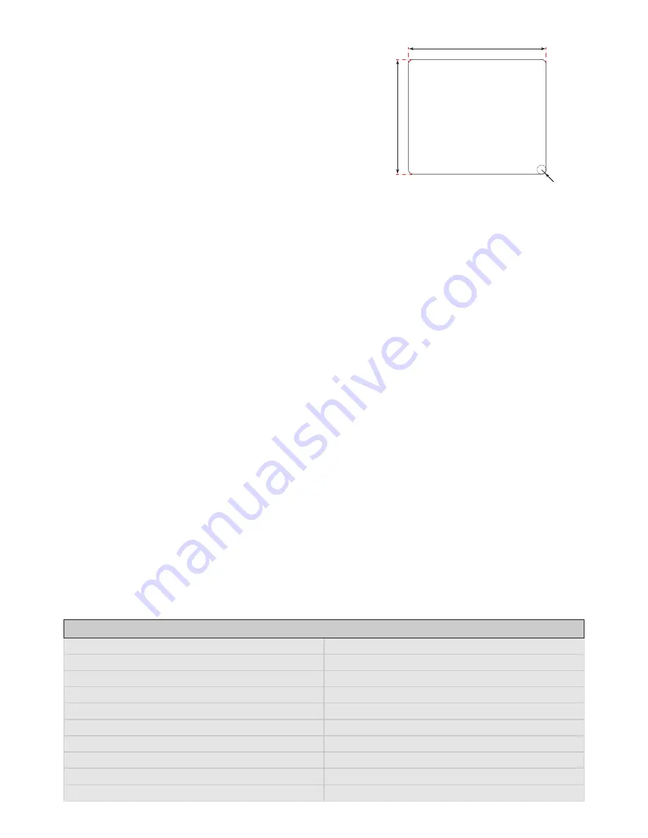
Control panel cut-out:
101mm x 121mm
Dimensions mm:
119mm x 99mm x 42mm
Front panel dimensions:
123.5mm x 105mm
3
Issue 1.2
5. Adjust the “Extension Limit” dial to suit the operational
requirement (see the “Operation” section).
6.
Replace the back cover and 4 screws on the face of the
E313.
7.
Seat the E313 in the control panel.
8.
Replace the mounting bracket and tighten the bracket
screws to securely hold the E313 in place.
9. NOTE
: Do not over-tighten the screws!
Figure 2
Panel cut-out
121 mm
101 mm
R 4 mm
(max)
PANEL CUT-OUT


