background image

DCA-70USI (60 Hz)  — OPERATION AND PARTS MANUAL — REV. #0  (01/04/06) — PAGE 81

1

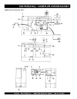
DCA-70USI (60 Hz)  — NAME PLATE  AND DECALS ASSY.

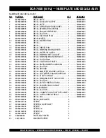
NAMEPLATE AND DECALS ASSY.

NO.

PART NO.

PART NAME

QTY.

REMARKS

1

M1550000204

DECAL; NOTE ................................................. 1 ............. M15000020

2

M1550002203

DECAL; AUXILIARY OUTPUT ......................... 1 ............. M15000220

3

M2550000304

DECAL; NOTE ................................................. 1 ............. M25000030

4

M2550000703

DECAL; OPERATING PROCEDURES ............ 1 ............. M25000070

5

M2550000803

DECAL; GENERATOR CONTROL ................... 1 ............. M25000080

6

M2550000903

DECAL; ENGINE OPERATING ....................... 1 ............. M25000090

7

M3550002204

DECAL; CAUTION ........................................... 1 ............. M35000220

8

M9500000004

DECAL; OIL DRAIN PLUG .............................. 1 ............. M90000000

9

M9500100004

DECAL; WATER ............................................... 1 ............. M90010000

10

M9500100104

DECAL; WATER DRAIN ................................... 1 ............. M90010010

11

M9500300004

DECAL; - ......................................................... 1 ............. M90030000

12

M9500300104

DECAL; + ........................................................ 1 ............. M90030010

13

M9500500004

DECAL; DIESEL FUEL .................................... 1 ............. M90050000

14

M9503000004

DECAL; WARNING MOVING PARTS .............. 2 ............. M90300000

15

M9503000103

DECAL; WATER-OIL CHECK ........................... 1 ............. M90300010

16

M9503100004

DECAL; WARNING HOT COOLANT ................ 1 ............. M90310000

17

M9503200004

DECAL; WARNING ENGINE EXHAUST .......... 1 ............. M90320000

18

M9510000004

DECAL; FULID DRAIN .................................... 1 ............. M91000000

19

M9510100004

DECAL; CAUTION HOT PARTS ...................... 1 ............. M91010000

20

M9510100304

DECAL; ENVIRONMENTAL WARNING ........... 1 ............. M91010030

21

M9510100403

DECAL; CAUTION ........................................... 1 ............. M91010040

22

M9520000004

DECAL; GROUND ........................................... 1 ............. M92000000

23

M9520000104

DECAL; AMMETER CHANGE-OVER SW. ...... 1 ............. M92000010

24

M9520000204

DECAL; VOLTMETER CHANGE-OVER SW. ... 1 ............. M92000020

25

M9520000504

DECAL; START CONTACT .............................. 1 ............. M92000050

26

M9520100004

DECAL; WARNING ELECT. SHOCK HAZ. ...... 1 ............. M92010000

27

M9520100204

DECAL; CAUTION ........................................... 1 ............. M92010020A

28

M9520100304

DECAL; SAFETY INSTRUCTIONS ................. 1 ............. M92010030

29

M9520100404

DECAL; DANGER HIGH VOLTAGE ................. 1 ............. M92010040

30

M9520100503

DECAL; WARNING .......................................... 1 ............. M92010050

31

M9520100603

DECAL; CAUTION ........................................... 2 ............. M92010060

32

M9520200003

DECAL; CONNECTION OF OUTPUT CABLE . 1 ............. M92020000

33

M9520200404

DECAL; OVER CURRENT RELAY .................. 1 ............. M92020040

34

M9512200004

DECAL; MQ ..................................................... 1 ............. M91220000

35

M9510200304

DECAL; MQ POWER

2

36

M2560101104

STRIPE

2

37

M2560100603

STRIPE; WHISPERWATT

2

38

M3560102204

STRIPE

2

39

M2560101303

STRIPE; 70

1

40

M2561002504

STRIPE; 70

1

41

M3560102504

STRIPE

2

42

0600500092

PLATE; MQ POWER

1

43

0021106016

MACHINE SCREW

4

Содержание MQ POWER WhisperWatt DCA70USI

Страница 1: ...RTS AND OPERATION MANUAL OPERATION AND PARTS MANUAL Revision 0 01 04 06 THIS MANUAL MUST ACCOMPANY THE EQUIPMENT AT ALLTIMES ULTRA SILENTTM SERIES MODEL DCA 70USI 60 Hz GENERATOR PARTS LIST NO M2900000314 ...

Страница 2: ...PAGE 2 DCA 70USI 60 Hz OPERATION AND PARTS MANUAL REV 0 01 04 06 ...

Страница 3: ...ations are based on the DCA 70USI 60 Hz Ultra Silent Generator Multiquip Inc reserves the right to discontinue or change specifications design or the information published in this publication at any time without notice and without incurring any obligations To find the latest revision of this publication visit our website at www mqpower com HERE S HOW TO GET HELP PLEASE HAVETHE MODEL AND SERIAL NUM...

Страница 4: ...rminal Panel Familiarization 24 26 Load Application 27 Generator Outputs 28 GaugeReading 29 OutputTerminal Panel Connections 30 31 Pre Setup 32 35 Generator Start up Procedure Manual 36 37 Generator Start up Procedure Auto Mode 38 Generator Shut Down Procedure 38 Maintenance Engine 39 40 Maintenance Trailer 41 44 TrailerWiring Diagram 45 GeneratorWiring Diagram 46 EngineWiring Diagram 47 Generator...

Страница 5: ... web parts order system or by fax qualify for the following extra discounts Ordered Standard Stock orders via orders 750 list and above Fax 3 10 Web 5 10 Special freight allowances when you order 10 or more line items via Web or Fax FedEx Ground Service at no charge for freight No other allowances on freight shipped by any other carrier Common nuts bolts and washers all items under 1 00 list price...

Страница 6: ... w o P 8 0 1 r e w o P C A x u A z H 0 6 e s a h P e l g n i S e g a t l o V V 0 2 1 t u p t u O 2 x W K 4 2 W K 8 4 s n o i t a c i f i c e p S e n i g n E 2 e l b a T l e d o M T 1 G B 4 F F U Z U S I e p y T d e g r a h c o b r u t n o i t c e j n i t c e r i d d e l o o c r e t a w e l c y c 4 s r e d n i l y C f o o N s r e d n i l y c 4 e k o r t S x e r o B m m 5 2 1 x m m 5 0 1 n i 2 9 4 x...

Страница 7: ... O I S N E M I D 3 E L B A T e c n e r e f e R r e t t e L m m n i n o i s n e m i D r e t t e L e c n e r e f e R m m n i n o i s n e m i D A m m 0 9 7 n i 0 1 1 3 F m m 0 7 6 2 n i 1 1 5 0 1 B m m 6 6 7 n i 5 1 0 3 G m m 5 3 7 1 n i 0 3 8 6 C m m 6 6 7 n i 5 1 0 3 H m m 0 5 9 n i 0 4 7 3 D m m 6 6 7 n i 5 1 0 3 E m m 6 6 7 n i 5 1 0 3 ...

Страница 8: ...ections Gasoline engine exhaust gases contain poisonous carbon monoxide This gas is colorless and odorless and can cause DEATH if inhaled NEVER operate this equipment in a confined area or enclosed structure that does not provide ample free flow air Gasoline is extremely flammable and its vapors can cause an explosion if ignited DO NOT start the engine near spilled fuel or combustible fluids DO NO...

Страница 9: ...e surrounding environment Thisgenerator otherproperty or the surrounding environment could be damaged if you do not follow instructions NOTE NEVER tamper with the factory settings of the engine governor or settings Personal injury and damage to the engine or equipment can result if operating in speed ranges above maximum allowable CAUTION OVER SPEED CONDITIONS CAUTION ACCIDENTAL STARTING CAUTION R...

Страница 10: ...l may lead to serious injury or even DEATH This equipment is to be operated by trained and qualified personnel only This equipment is for industrial use only DANGER READTHIS MANUAL ALWAYS check the machine for loosened threads or bolts before starting NEVERoperatethegeneratorinanexplosiveatmosphere or near combustible materials An explosion or fire could result causing severe bodily harm or even d...

Страница 11: ...the equipment it is important to provide a good EARTH ground Article 250 Grounding of the National Electrical Code NEC providesguidelinesforpropergroundingandspecifies that the cable ground shall be connected to the grounding system of the building as close to the point of cable entry as practical The following safety recommendations should also be followed ALWAYS make sure generator is properly g...

Страница 12: ...to gush out of the radiator causing severe scalding to any persons in the general area of the generator Coolant Drain Plug Removing the coolant drain plug while the engine is hot will result in hot coolant gushing out of the coolant drain plug therefore causing severe scalding to any persons in the general area of the generator Engine Oil Drain Plug Removing the engine oil drain plug while the eng...

Страница 13: ...s bumper to prevent tipping while parked Avoid sharp turns to prevent rolling DO NOT transport generator with fuel in tank Towing Transporting Safety To reduce the possibility of an accident while transporting the generator on public roads always make sure the trailer that supports the generator and the towing vehicle are in good operating condition and both units are mechanically sound The follow...

Страница 14: ...ety decals Figures 2 3 These decals are provided for operator safety and maintenance information The illustration below and on the preceding page show the decals as they appear on the machine Should any of these decals become unreadable replacements can be obtained from your dealer DCA 70USI 60 Hz GENERATOR DECALS Figure 2 Generator Decals ...

Страница 15: ...DCA 70USI 60 Hz OPERATION AND PARTS MANUAL REV 0 01 04 06 PAGE 15 1 DCA 70USI 60 Hz GENERATOR DECALS Figure 3 Generator Decals Cont inued ...

Страница 16: ...PAGE 16 DCA 70USI 60 Hz OPERATION AND PARTS MANUAL REV 0 01 04 06 Figure 4 Typical Generator Grounding Application DCA 70USI 60 Hz INSTALLATION ...

Страница 17: ...mm2 or larger b Aluminum 8 AWG 8 4 mm2 or larger 2 When grounding the generator Figure 4 connect the ground cable between the lock washer and the nut on the generator and tighten the nut fully Connect the other end of the ground cable to earth ground 3 NEC article 250 52 c specifies that the earth ground rod should be buried aminimumof8ft intotheground When connecting the generator to any building...

Страница 18: ...ections of the open delta A B C and D Duringsteadystateloads thepowerfromthevoltageregulator is supplied from the parallel connections of A to B A to D and C to D These three phases of the voltage input to the voltage regulator are then rectified and are the excitation current for the exciter section When a heavy load such as a motor starting or a short circuit occurs the automatic voltage regulat...

Страница 19: ...M E T I N O I T P I R C S E D 1 y l b m e s s A r e l f f u M 2 y l b m e s s A e n i g n E 3 y l b m e s s A e r u s o l c n E 4 y l b m e s s A r o t a r e n e G 5 y l b m e s s A l a n i m r e T t u p t u O 6 y l b m e s s A k n a T l e u F 7 y l b m e s s A y r e t t a B 8 y l b m e s s A l e n a P l o r t n o C r o t a r e n e G 9 y l b m e s s A l e n a P g n i t a r e p O e n i g n E ...

Страница 20: ...PAGE 20 DCA 70USI 60 Hz OPERATION AND PARTS MANUAL REV 0 01 04 06 NOTE PAGE ...

Страница 21: ...t the U V and W OutputTerminal Lugs 6 Voltmeter Change Over Switch This switch allows the AC voltmeter to indicate phase to phase voltage between any two phases of the output terminals or to be switched off 7 Voltage Regulator Control Allows 15 manual adjustment of the generator s output voltage Located behind the generator control panel is the Generator Control Box This box contains some of the n...

Страница 22: ...PAGE 22 DCA 70USI 60 Hz OPERATION AND PARTS MANUAL REV 0 01 04 06 Figure 7 Engine Operating Panel DCA 70USI 60 Hz ENGINE OPERATING PANEL ...

Страница 23: ...run When this switch is set to the MANUAL position the generator will start immediately If the generator is to be connected to a building s AC power source via a transfer switch isolation place the switch in the AUTO position In this position the generator will monitor the AC line output from the building s power source B Low Oil Pressure Indicates the engine pressure has fallen below 15 psi The o...

Страница 24: ...120V GFCI receptacles 20 amp Two 2 GFCI Circuit Breakers 20 amps Five 5 Output Terminal Lugs U V W O Ground OutputTerminal Panel TheOutputTerminalPanel Figure8 shownbelowislocated ontheright handside leftfromcontrolpanel ofthegenerator Lift up on the cover to gain access to receptacles and terminal lugs NOTE Terminal legs O and Ground areconsideredbondedgrounds Figure 8 OutputTerminal Panel DCA 70...

Страница 25: ...current on all three receptacles is dependent on the load requirements of the OutputTerminal Lugs Turn the voltage regulator control knob Figure 11 on the control panel to obtain the desired voltage Turning the knob clockwise will increasethe voltage turning the knob counter clockwise will decrease the voltage Figure 10 120 240VTwist Lock Auxiliary Receptacles DCA 70USI 60 Hz OUTPUT TERMINAL PANEL...

Страница 26: ... both the circuit breaker and the over current relay may trip If the circuit breaker can not be reset the reset button on the over cur rent relay must be pressed The over current relay is lo cated in the control box Figure 14 Over Current Relay Blower Fan This unit has an intake fan located at the rear of the machine to draw outside air into the cabinet to cool the engine The fan has a 10 amp AC f...

Страница 27: ...close attention to the required starting current capacity NOTE WATTS VOLTAGE x AMPERAGE Three Phase Load When calculating the power requirements for 3 phase power use the following equation NOTE An inadequate size connecting cable which cannot carry the required load can cause a voltage drop which can burn out the appliance or tool and overheat the cable See Table 5 NOTE Before connecting this gen...

Страница 28: ... v A s p m A t n e r r u C V 0 2 1 0 4 2 Ø 1 A M E N x e l p u D I C F G V 0 2 1 R 0 2 5 4 0 4 0 2 9 3 e l c a t p e c e r r e p s p m a 5 0 8 3 e l c a t p e c e r r e p s p m a 0 1 8 6 3 e l c a t p e c e r r e p s p m a 5 1 6 5 3 e l c a t p e c e r r e p s p m a 0 2 3 0 1 e l b a T Ø y t i l i b a p a C d a o L e l c a t p e c e R I C F G e s U n i A V K s l a n i m r e T O W V U d a o L e l b...

Страница 29: ...Phase 240 139 position Figure 21 AC Ammeter Amp reading on U lug Figure 20 AC Ammeter Change Over Switch The ammeter gauge will only show a reading when the Output Terminal Lugs are connected to a load and in use NOTE ReadingVoltage To determine the voltage between two terminal lugs set the AC Voltmeter Change Over Switch to the appropriate setting Figure 18 to activate the AC Voltmeter Gauge Figu...

Страница 30: ...3 OutputTerminal Lugs 3Ø 240 139V Connections 2 Connect the load wires to the OutputTerminal Lugs as shown in Figure 23 3 Turn the voltage regulator knob Figure 23 clockwise to increase voltage output turn counterclockwise to decrease voltage output 3Ø 208V 1Ø120V OutputTerminal LugVoltages 1 Place the voltage selector switch in the 3Ø 240 139 position as shown in Figure 25 Figure 24 Voltage Regul...

Страница 31: ...gulator knob Figure 24 clockwise to increase voltage output turn counterclockwise to decrease voltage output 1Ø 240V 120V OutputTerminal LugVoltages 1 Place the voltage selector switch in the 1Ø 240 120 position as shown in Figure 29 2 Connect the load wires to the OutputTerminal Lugs as shown in Figure 30 3 Turn the voltage regulator knob Figure 25 clockwise to increase voltage output turn counte...

Страница 32: ... the OFF position prior to starting the engine Lubrication Oil Fill the engine crankcase with lubricating oil through the filler hole but DO NOT overfill Make sure the generator is level and verify that the oil level is maintained between the two notches Figure 31 on the dipstick See Table 11 for proper selection of engine oil Figure 32 Internal FuelTank System Refilling the Fuel System Fuel Check...

Страница 33: ...r neck Figure 35 Figure 35 Full Fuel Tank Figure 36 Fuel Expansion 3 Open cabinet doors on the right side of the generator fromgeneratorcontrolpanelposition Removefuelcap and fill tank Figure 34 Figure 34 Fueling the Generator ALWAYS place trailer on firm level ground before refueling to prevent spilling and maximize the amount of fuel that can be pumped into the tank CAUTION REFUELINGTHE GENERATO...

Страница 34: ... and the negative battery terminal disconnected Air Cleaner Periodic cleaning replacement is necessary Inspect it in accordance with the ISUZU Engine Owner s Manual Fan BeltTension A slack fan belt may contribute to overheating or to insufficient charging of the battery Inspect the fan belt for damage and wear and adjust it in accordance with the ISUZU Engine Owner s Manual The fan belt tension is...

Страница 35: ...l hose clamps and check hoses for leaks If any hose fuel or oil lines are defective replace them immediately If the battery cable is connected incorrectly electricaldamagetothe generator will occur Pay close attention to the polarity of the battery when connecting the battery NOTE Battery This unit is of negative ground DO NOT connect in reverse Always maintain battery fluid level between the spec...

Страница 36: ...hard wire hookup panel 3 The output terminal lugs are protected by a plastic cover Remove this cover to gain access to the terminals Tighten terminal nuts securely to prevent load wires from slipping out 4 Close all engine enclosure doors Figure 40 Figure 39 Main Aux and GFCI Circuit Breakers OFF NEVER manually start the engine with the main GFCI or auxiliary circuit breakers in the ON closed posi...

Страница 37: ...r the engine has been started Figure 45 Engine Running LED ON Figure 52 Engine Tachometer Gauge 16 The tachometer gauge Figure 52 will indicate the speed of the engine when the generator is operating Undernormaloperating conditions this speed is approximately 1800 RPM s 15 The coolanttemperaturegauge Figure 51 will indicate the coolant temperature Under normal operating conditions the coolant temp...

Страница 38: ...ed in the ManualStart up procedure start at step 9 Figure 55 MPEC Control Switch AUTO When the generator is set in the AUTO mode the generator will automically start in the event of comercial power falling below a prescribed level by means of a contact closure that is generated automatically by a transfer switch NOTE Starting Auto Mode Before connecting this generator to any building s electrical ...

Страница 39: ...rvice After changing the air element press the dust indicator button to reset the indicator E C N A N E T N I A M N O I T C E P S N I 4 1 E L B A T s r H 0 1 Y L I A D s r H 0 5 2 s r H 0 0 5 s r H 0 0 0 1 E N I G N E s l e v e L d i u l F e n i g n E k c e h C X r e n a e l C r i A k c e h C X l e v e L d i c A y r e t t a B k c e h C X n o i t i d n o C t l e B n a F k c e h C X s k a e L r o f ...

Страница 40: ...r after disassembling the fuel system bleed the system according to the following procedure See the ISUZU Engine Manual for details To restart after running out of fuel turn the switch to the ON position for 15 30 seconds Try again if needed This unit is equipped with an automatic air bleeding system Check Oil Level Check the crankcase oil level prior to each use or when the fuel tank is filled In...

Страница 41: ...When using the generator in hot climates there is no reason to apply power to jacket water heater However if the generator will be used in cold climates it is always a good idea to apply power to the jacket water heater at all times To apply power to the jacket water heater simply apply power to the jacket water heater receptacle via commercial power using an power cord of adequate size If the gen...

Страница 42: ...nectors looms are provided with the trailer so the brake lights and turn signals can be connected to the towing vehicle 16 Application Indicates which units can be employed on a particular trailer Trailer Maintenance This section is intended to provide the user with generic trailer service and maintenance information The service and maintenance guidelines referenced in this section refer to a wide...

Страница 43: ...aulicsurgebrakingrequirestheinstallationofanactuator at the tongue of the trailer Remember the surge or push of the trailer toward the tow vehicle automatically synchronizes the trailer brakes with the tow vehicle brakes As the trailer pushes against the tow vehicle the actuator telescopes together and applies force to the master cylinder supplying hydraulic pressure to the trailer brakes Periodic...

Страница 44: ...d loosening of fasteners Replace all damaged parts suspension immediately Torqued suspension components as detailed in Table 17 Figure 59 Major Suspension Components DCA 70USI 60 Hz TRAILER MAINTENANCE DO NOT attempt to repair or modify a wheel DO NOT install in inner tube to correct a leak through the rim If the rimiscracked theairpressureintheinner tube may cause pieces of the rim to explode bre...

Страница 45: ...ent of the wheels is as follows 1 Start all wheel lug nuts by hand 2 Torque all lug nuts in sequence see Figure 60 DO NOT torque the wheel lug nuts all the way down Tighten each lug nut in 3 separate passes as defined by Table 18 3 After first road use retorque all lug nuts in sequence Check all wheel lug nuts periodically s t n e m e r i u q e R e u q r o T e r i T 8 1 e l b a T e z i S l e e h W...

Страница 46: ...PAGE 46 DCA 70USI 60 Hz OPERATION AND PARTS MANUAL REV 0 01 04 06 DCA 70USI 60 Hz TRAILERWIRING DIAGRAM Figure 61 Trailer Towing Vehicle Wiring Diagram ...

Страница 47: ...DCA 70USI 60 Hz OPERATION AND PARTS MANUAL REV 0 01 04 06 PAGE 47 1 NOTE PAGE ...

Страница 48: ...PAGE 48 DCA 70USI 60 Hz OPERATION AND PARTS MANUAL REV 0 01 04 06 DCA 70USI 60 Hz GENERATORWIRING DIAGRAM Figure 62 GeneratorWiring Diagram ...

Страница 49: ...DCA 70USI 60 Hz OPERATION AND PARTS MANUAL REV 0 01 04 06 PAGE 49 1 DCA 70USI 60 Hz ENGINEWIRING DIAGRAM Figure 63 Engine Wiring Diagram ...

Страница 50: ... i t a t o R e v i t c e f e D e c a l p e r d n a k c e h C d l e i F r e t i c x E e v i t c e f e D 1 N C n o K J s s o r c a s m h o 3 7 1 r o f k c e h C t u p t u O e g a t l o V w o L t c e r r o c d e e p s e n i g n e s I h g i H o t r e v e l e l t t o r h t e n i g n e n r u T e s o o l s n o i t c e n n o c g n i r i w s I r i a p e r d n a g n i r i w k c e h C R V A e v i t c e f e D...

Страница 51: ... o o c h g i H n o s i t h g i l t c e r r o c n i n o i s n e t t l e b n a F t l e b n a f e c a l p e r n e t h g i T r o t a i d a r h g u o r h t n o i t a l u c r i c t o n s i w o l f r i A l l i r g r o t a i d a r r i a p e r n a e l C n e p o s r o o D s r o o d e s o l C g n i k a e l t s u a h x E t r a p y t l u a f r o s t e k s a g r i a p e r e c a l p e R d e d a o l r e v o g n i...

Страница 52: ...cular part is used Model Number Where indicated this shows that the corresponding part is utilized only with this specific model number or model number variant Items Found In the Items Number Column All parts with same symbol in the number column or belong to the same assembly or kit If more than one of the same reference number is listed the last one listed indicates newest or latest part availab...

Страница 53: ...0USI 60 Hz WHISPERWATTGENRATOR W ISUZU FF4BG1T DIESEL ENGINE 1TO 3 UNITS Qty P N Description 5 1132402311 FILTER OIL 5 1132400791 FILTER FUEL PRIMARY 3 0602046365 ELEMENT AIR 1 8972333820 BELT FAN 1 0605505070 CAP FUEL TANK 1 0602122272 UNIT OIL PRESSURE 1 0602123260 UNIT WATER TEMPERATURE 2 0601802149 FUSE 10A 1 8971256000 SENDER WATER SWITCH ENGINE SIDE 1 9827200690 SENDER OIL SWITCH ENGINE SIDE...

Страница 54: ...PAGE 54 DCA 70USI 60 Hz OPERATION AND PARTS MANUAL REV 0 01 04 06 DCA 70USI 60 HZ GENERATOR ASSY GENERATOR ASSY ...

Страница 55: ...T KIT 1 1 17 0071906311 BEARING 1 6311DDUC3 2 M2163400103 COUPLING RING 1 3 M9200100204 REAMER BOLT 2 4 0010310030 HEX HEAD BOLT 7 5 0042510000 SPRINGWASHER 9 6 B5130000103 STATOR ASSY 1 B5134000304 7 0845041904 GROMMET 2 8 8191315292 END BRACKET 1 9 8101350013 FIELD ASSY EXCITER 1 B5134000304 10 0012110070 HEX HEAD BOLT 4 S 26 11 0042610000 SPRINGWASHER 4 12 0041210000 PLAINWASHER 4 13 0017110035...

Страница 56: ...PAGE 56 DCA 70USI 60 Hz OPERATION AND PARTS MANUAL REV 0 01 04 06 DCA 70USI 60 Hz CONTROL BOX ASSY CONTROL BOX ASSY ...

Страница 57: ...COVER 1 15 0016906016 HEX HEAD BOLT 4 16 M2270100004 SELECTOR SWITCH 1 16A M1201000004 KNOB SELECTOR SWITCH 17 M2213600803 SWITCH BRACKET 1 18 0330000320 EDGING 2 19 0027104010 MACHINE SCREW 4 20 0016906016 HEX HEAD BOLT 6 21 M2213600904 SWITCH COVER 1 22 0016906016 HEX HEAD BOLT 4 23 0015906016 HEX HEAD BOLT 8 23A 0040506000 TOOTHEDWASHER 1 24 M2223000703 CONTROL PANEL 1 25 0601807641 FREQUENCY M...

Страница 58: ...PAGE 58 DCA 70USI 60 Hz OPERATION AND PARTS MANUAL REV 0 01 04 06 DCA 70USI 60 Hz CONTROL BOX ASSY CONT CONTROL BOX ASSY ...

Страница 59: ...9220100004 SET SCREW 2 50 0080200007 SNAP RING 2 51 1825530401 STARTER RELAY 1 REPLACES P N 0602200304 52 0016906016 MACHINE SCREW 2 53 LY2DDC12V RELAY 1 53A PTF08AE BASE 1 53B PYCA1 CAP 2 54 0027104020 MACHINE SCREW 2 55 0601823240 RECTIFIER DE45 1 56 0027104020 MACHINE SCREW 1 57 0601827680 STARTER RELAY 1 58 0027104020 MACHINE SCREW 2 59 0602202546 CONTROLLER EGS DYN1 1 60 0027105016 MACHINE SC...

Страница 60: ...PAGE 60 DCA 70USI 60 Hz OPERATION AND PARTS MANUAL REV 0 01 04 06 DCA 70USI 60 Hz ENGINE AND RADIATOR ASSY ENGINE AND RADIATOR ASSY ...

Страница 61: ...11053 CAP RADIATOR 1 11 M9312200104 MOUNT RUBBER 2 12 0016908040 HEX HEAD BOLT 2 13 0207008000 HEX NUT 2 14 M2310500803 RADIATOR HOSE 1 15 M2310500903 RADIATOR HOSE 1 16 0605515147 HOSE BAND 2 17 0605515199 HOSE BAND 2 18 M2313300404 FAN BRACKET 1 19 0017110030 HEX HEAD BOLT 4 20 0601822798 FAN MOTOR 1 21 0017110030 HEX HEAD BOLT 4 22 0602046582 AIR CLEANER 1 22A 0602046365 ELEMENT AIR CLEANER 1 2...

Страница 62: ...PAGE 62 DCA 70USI 60 Hz OPERATION AND PARTS MANUAL REV 0 01 04 06 DCA 70USI 60 Hz ENGINE AND RADIATOR ASSY CONT ENGINE AND RADIATOR ASSY ...

Страница 63: ...R 1 43 0603300285 ROCKNUT 1 44 0605511395 VALVE 1 45 0603306395 HOSE JOINT 1 46 0602021070 CAP 1 47 0269200420 DRAIN HOSE 1 48 M9300000203 RESERVE TANK 1 49 0602010900 CAP RESERVE TANK 1 50 M3316100303 BRACKET RESERVE TANK 1 51 0016908020 HEX HEAD BOLT 3 52 0199102000 HOSE 1 53 0193600700 HOSE 1 54 0605515106 HOSE BAND 3 55 0017112025 HEX HEAD BOLT 1 56 0040512000 TOOTHEDWASHER 1 57 0602220911 CLA...

Страница 64: ... Hz OUTPUTTERMINAL ASSY OUTPUT TERMINAL ASSY THE SERIAL NUMBER MAY BE REQUIRED ADD THE FOLLOWING DIGITS AFTER THE PART NUMBER WHEN ORDERING ANY PAINTED PANEL TO INDICATE COLOR OF UNIT 1 ORANGE 5 BLACK 2 WHITE 6 CATERPILLAR YELLOW 3 SPECTRUM GREY 7 CATO GOLD 4 SUNBELT GREEN 8 RED ...

Страница 65: ...003000 HEX NUT 4 13 0016906020 HEX HEAD BOLT 2 14 0016906016 HEX HEAD BOLT 4 15 M3236400004 CABLE OUTLET COVER 1 16 M3236300004 SUPPORTER CABLE OUTLET COVER 1 17 0016906020 HEX HEAD BOLT 6 18 0601870440 CIRCUIT BREAKER 1 POLE 20A 2 19 0601870441 CIRCUIT BREAKER 2 POLE 50A 3 20 M1260700504 BREAKER FITTING COVER 1 20A 0222100100 CUSHION RUBBER 2 21 0016906020 HEX HEAD BOLT 2 22 0601812598 RECEPTACLE...

Страница 66: ...PAGE 66 DCA 70USI 60 Hz OPERATION AND PARTS MANUAL REV 0 01 04 06 DCA 70USI 60 Hz BATTERY ASSY BATTERY ASSY ...

Страница 67: ...T NO PART NAME QTY REMARKS 1 0602220187 BATTERY 627MFD 1 2 M9210500014 BATTERY SHEET 1 3 M9103000304 BATTERY BAND 1 4 0602220920 BATTERY BOLT SET 2 5 M2346900404 BATTERY CABLE 1 6 M2346900104 BATTERY CABLE 1 7 CABLE 1 MAKE LOCALLY 8 0017112025 HEX HEAD BOLT 1 8A 0040512000 TOOTHEDWASHER 1 9 0040520000 TOOTHEDWASHER 1 ...

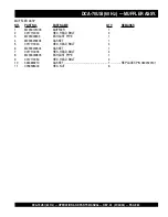
Страница 68: ...PAGE 68 DCA 70USI 60 Hz OPERATION AND PARTS MANUAL REV 0 01 04 06 DCA 70USI 60 Hz MUFFLER ASSY MUFFLER ASSY ...

Страница 69: ...AME QTY REMARKS 1 M2330101003 MUFFLER 1 2 0017112030 HEX HEAD BOLT 4 3 M233000903 EXHAUST PIPE 1 4 M2333200404 GASKET 1 5 0017110040 HEX HEAD BOLT 4 6 M2333200304 GASKET 1 7 0017110035 HEX HEAD BOLT 4 8 M2333000803 EXHAUST PIPE 1 9 0017110050 HEX HEAD BOLT 4 10 3943690210 GASKET 1 REPLACES P N 0602320101 11 0039308000 HEX NUT 6 ...

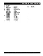
Страница 70: ...PAGE 70 DCA 70USI 60 Hz OPERATION AND PARTS MANUAL REV 0 01 04 06 DCA 70USI 60 Hz FUELTANK ASSY FUEL TANK ASSY ...

Страница 71: ...05505070 FUEL TANK CAP 1 1B 0605501079 FUEL SENDER UNIT 1 1C 0605516090 GASKET 1 2 M2363200704 TANK BAND 6 3 M9310500104 SUPPORTER SHEET 6 4 0016908020 HEX HEAD BOLT 6 5 0016908055 HEX HEAD BOLT 3 5A 0207008000 HEX NUT 9 6 0191302200 VENT HOSE 1 7 0605515109 HOSE BAND 2 8 0191300900 SUCTION HOSE 1 9 0191301100 RETURN HOSE 1 10 0605515109 HOSE BAND 4 11 0222100710 TANK SHEET 5 ...

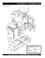
Страница 72: ...AL NUMBER MAY BE REQUIRED ADD THE FOLLOWING DIGITS AFTER THE PART NUMBER WHEN ORDERING ANY PAINTED PANEL TO INDICATE COLOR OF UNIT 1 ORANGE 5 BLACK 2 WHITE 6 CATERPILLAR YELLOW 3 SPECTRUM GREY 7 CATO GOLD 4 SUNBELT GREEN 8 RED DCA 70USI 60 Hz ENCLOSURE 1 ASSY ENCLOSURE 1 ASSY ...

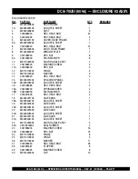
Страница 73: ...BOLT 6 13 M2310600204 HOSE COVER 1 14 M2310600304 HOSE COVER 1 15 M2310600004 HOSE COVER 1 16 0016906020 HEX HEAD BOLT 12 17 M3423200704 DUCT COVER 2 18 0016906020 HEX HEAD BOLT 14 19 M3423200804 DUCT COVER 1 20 0016906016 HEX HEAD BOLT 6 21 M2310300704 FAN SHROUD 1 22 M2310300804 FAN SHROUD 1 23 M2310300904 FAN SHROUD 1 24 0016906020 HEX HEAD BOLT 14 25 M2423300204 DISCHARGE GUIDE 1 25A M24931045...

Страница 74: ...0 Hz ENCLOSURE 1 ASSY CONT THE SERIAL NUMBER MAY BE REQUIRED ADD THE FOLLOWING DIGITS AFTER THE PART NUMBER WHEN ORDERING ANY PAINTED PANEL TO INDICATE COLOR OF UNIT 1 ORANGE 5 BLACK 2 WHITE 6 CATERPILLAR YELLOW 3 SPECTRUM GREY 7 CATO GOLD 4 SUNBELT GREEN 8 RED ENCLOSURE 1 ASSY ...

Страница 75: ...OLT 12 36 M2463200503 DUCT 1 36A M2493502704 ACOUSTIC SHEET 1 37 0016908020 HEX HEAD BOLT 10 38 M2463400103 DUCT COVER 1 39 0016908020 HEX HEAD BOLT 6 40 M2423201504 OVER COVER FRONT FRAME 1 40A M2493104404 ACOUSTIC SHEET 1 41 0019208020 HEX HEAD BOLT 42 42 0019210025 HEX HEAD BOLT 8 43 M3310600004 COVER RADIATOR CAP 1 44 0019208020 HEX HEAD BOLT 4 45 M2483100304 COVER EXHAUST PIPE 1 46 0016908020...

Страница 76: ...I 60 Hz ENCLOSURE 2 ASSY ENCLOSURE 2 ASSY THE SERIAL NUMBER MAY BE REQUIRED ADD THE FOLLOWING DIGITS AFTER THE PART NUMBER WHEN ORDERING ANY PAINTED PANEL TO INDICATE COLOR OF UNIT 1 ORANGE 5 BLACK 2 WHITE 6 CATERPILLAR YELLOW 3 SPECTRUM GREY 7 CATO GOLD 4 SUNBELT GREEN 8 RED ...

Страница 77: ...10100204 HINGE 2 13 M9116100004 WASHER 2 14 0019208020 HEX HEAD BOLT 3 15 M2453201202 SPLASHER PANEL 1 15A M2493405204 ACOUSTIC SHEET 1 16 0019108065 HEX HEAD BOLT 4 16A 0042308000 SPRINGWASHER 4 16B 0042408000 PLAINWASHER 4 17 0016910025 HEX HEAD BOLT 2 18 M2453001703 SIDE DOOR 1 18A M2493404704 ACOUSTIC SHEET 1 19 M2453001803 SIDE DOOR 1 19A M2493405104 ACOUSTIC SHEET 1 20 M2453001903 SIDE DOOR ...

Страница 78: ...PAGE 78 DCA 70USI 60 Hz OPERATION AND PARTS MANUAL REV 0 01 04 06 DCA 70USI 60 Hz RUBBER SEALS ASSY RUBBER SEALS ASSY ...

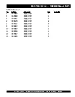
Страница 79: ... 0314502250 RUBBER SEAL 1 3 0229200950 RUBBER SEAL 3 4 0229200125 RUBBER SEAL 4 5 0228901165 RUBBER SEAL 3 6 0228900770 RUBBER SEAL 8 7 0228901105 RUBBER SEAL 3 8 0228900535 RUBBER SEAL 1 9 0228900475 RUBBER SEAL 1 10 0229200910 RUBBER SEAL 1 11 0228800525 RUBBER SEAL 1 12 0228800790 RUBBER SEAL 2 13 0228800475 RUBBER SEAL 1 14 0228100325 RUBBER SEAL 2 15 0228100420 RUBBER SEAL 2 ...

Страница 80: ...PAGE 80 DCA 70USI 60 Hz OPERATION AND PARTS MANUAL REV 0 01 04 06 DCA 70USI 60 Hz NAME PLATE AND DECALS ASSY NAMEPLATE AND DECALS ASSY ...

Страница 81: ...NG ENGINE EXHAUST 1 M90320000 18 M9510000004 DECAL FULID DRAIN 1 M91000000 19 M9510100004 DECAL CAUTION HOT PARTS 1 M91010000 20 M9510100304 DECAL ENVIRONMENTALWARNING 1 M91010030 21 M9510100403 DECAL CAUTION 1 M91010040 22 M9520000004 DECAL GROUND 1 M92000000 23 M9520000104 DECAL AMMETER CHANGE OVER SW 1 M92000010 24 M9520000204 DECAL VOLTMETER CHANGE OVER SW 1 M92000020 25 M9520000504 DECAL STAR...

Страница 82: ...icants g Decalsandpaperproducts h Itemspurchasedinkits 7 The sender will be notified of any materialreceivedthatisnotacceptable 8 Such material will be held for five workingdaysfromnotification pending instructions If a reply is not received within five days the material will be re turnedtothesenderathisexpense 9 Creditonreturnedpartswillbeissuedat dealer net price at time of the original purchase...

Страница 83: ...DCA 70USI 60 Hz OPERATION AND PARTS MANUAL REV 0 01 04 06 PAGE 83 1 NOTE PAGE ...

Страница 84: ...N HERE S HOW TO GET HELP PLEASE HAVETHE MODEL AND SERIAL NUMBERON HANDWHENCALLING MQ POWER CORPORATE OFFICE 18910 Wilmington Ave 800 421 1244 Carson CA 90746 FAX 310 632 2656 Email mqpower multiquip com Internet www mqpower com PARTS DEPARTMENT 800 427 1244 FAX 800 672 7877 310 537 3700 FAX 310 637 3284 SERVICE DEPARTMENT 800 835 2551 FAX 310 638 8046 310 537 3700 TECHNICALASSISTANCE 800 835 2551 ...

Отзывы: