background image

DCA-150SSKII — PARTS AND OPERATION  MANUAL— REV. #1  (05/08/01) — PAGE 17

s

t

n

e

m

e

ri

u

q

e

R

e

u

q

r

o

T

n

o

i

s

n

e

p

s

u

S

.

3

e

l

b

a

T

m

e

tI

).

s

b

L

-.

t

F

(

e

u

q

r

o

T

T

L

O

B

-

U

"

8

/

3

5

3

-

X

A

M

0

3

-

N

I

M

T

L

O

B

-

U

"

6

1

/

7

0

6

-

X

A

M

5

4

-

N

I

M

T

L

O

B

-

U

"

2

/

1

0

6

-

X

A

M

5

4

-

N

I

M

SHACKLE BOLT
SPRING EYE BOLT

SNUG FIT ONLY

.

PARTS MUST ROTATE FREELY

.

LOCKING NUTS OR COTTER PINS ARE PROVIDED TO
RETAIN NUT

-

BOLT ASSEMBLY

.

SHOULDER TYPE
SHACKLE BOLT

0

5

-

X

A

M

0

3

-

N

I

M

s

t

n

e

m

e

ri

u

q

e

R

e

u

q

r

o

T

e

ri

T

.

4

e

l

b

a

T

e

z

i

S

l

e

e

h

W

s

s

a

P

t

s

ri

F

S

B

L

-

T

F

s

s

a

P

d

n

o

c

e

S

S

B

L

-

T

F

s

s

a

P

d

ri

h

T

S

B

L

-

T

F

"

2

1

5

2

-

0

2

0

4

-

5

3

5

6

-

0

5

"

3

1

5

2

-

0

2

0

4

-

5

3

5

6

-

0

5

"

4

1

5

2

-

0

2

0

6

-

0

5

0

2

1

-

0

9

"

5

1

5

2

-

0

2

0

6

-

0

5

0

2

1

-

0

9

"

6

1

5

2

-

0

2

0

6

-

0

5

0

2

1

-

0

9

Lug Nut Torque Requirements
It is extremely important to apply and maintain proper wheel
mounting torque on the trailer.  Be sure to use only the
fasteners matched to the cone angle of the wheel.  Proper
procedure for attachement of the wheels is as follows:

1.    Start all wheel lug nuts by hand.
2.    Torque all lug nuts in sequence.  See Figure 5.  DO

NOT torque the wheel lug nuts all the way down.  Tighten
each lug nut in 3 separate passes as defined by Table
4.

3.      After first road use, retorque all lug nuts in sequence.

Check all wheel lug nuts periodically for continued safe
operaion.

NOTE

NEVER use an pneumatic air gun to
tighten wheel lug nuts.

DCA-150SSKII   — TRAILER TIRES  &  SUSPENSION

Figure 5. Lug Nut Tightening Sequence

Содержание DCA-150SSKII

Страница 1: ...S DEPARTMENT 18910 WILMINGTON AVE 800 427 1244 CARSON CALIFORNIA 90746 FAX 800 672 7877 310 537 3700 SERVICE DEPARTMENT 800 421 1244 800 835 2551 FAX 310 537 3927 FAX 310 638 8046 E mail mq multiquip com www multiquip com MQ POWER MODEL DCA 150SSKII PORTABLE GENERATOR PARTS AND OPERATION MANUAL ...

Страница 2: ...PAGE 2 DCA 150SSKII PARTS AND OPERATION MANUAL REV 2 05 08 01 ...

Страница 3: ...ODEL AND SERIAL NUMBER ON HANDWHEN CALLING PARTS DEPARTMENT 800 427 1244 or 310 537 3700 FAX 800 672 7877 or 310 637 3284 SERVICE DEPARTMENT 800 835 2551 or 310 537 3700 FAX 310 638 8046 WARRANTY DEPARTMENT 800 835 2551 or 310 537 3700 FAX 310 638 8046 MAIN 800 421 1244 or 310 537 3700 FAX 310 537 3927 ...

Страница 4: ...anel 28 29 Engine Operating Panel 30 31 Output Terminal Panel 32 39 Installation 40 41 Pre Setup 42 45 Load Application 46 Generator Start Up Procedure Manual 47 49 Generator Start Up Procedure Auto 50 Generator Shut Down Procedure 51 Maintenance 51 53 Troubleshooting Engine 54 55 Troubleshooting Generator Engine 56 Troubleshooting MPEC 57 Explanation Of Codes In Remarks Column 58 Suggested Spare ...

Страница 5: ...ude complete part numbers and are received by fax qualify for the following extra discounts Number of line items ordered Additional Discount 1 9 items 3 10 items 5 Now Direct TOLL FREE access to our Parts Department Toll free nationwide 800 421 1244 Toll free FAX 800 6 PARTS 7 800 672 7877 Dealer account number Dealer name and address Shipping address if different than billing address Return fax n...

Страница 6: ...pment should not be operated by persons under 18 years of age NEVERoperatethisequipmentwithoutproper protective clothing shatterproof glasses steel toed boots and other protective devices required by the job NEVER operate this equipment when not feeling well due to fatigue illness or taking medicine NEVERoperatethisequipmentunder the influence or drugs or alcohol NEVER use accessories or attachmen...

Страница 7: ... damage to the generator and electrical shock CAUTION DO NOT touch or open any of the below mentioned components while the generator is running Always allow sufficienttimefortheengineandgenerator to cool before performing maintenance Radiator 1 Radiator Cap Removing the radiator cap while the engine is hot will result in boiling water to gush out of the radiator therefore causing severe scalding t...

Страница 8: ... generator always use the balanced center point suspension hook and lift straight upwards NEVER allow any person or animal to stand underneath the machine while lifting When loading the generator on a truck be sure to use the front and back frame bars as a means to secure the generator during transport Battery Neveroverfillthebatterywithwaterabove the upper limit CAUTION The battery contains acids...

Страница 9: ...earest fire extinguisher andfirstaidkit Knowthelocationofthenearesttelephone Also know the phone numbers of the nearest ambulance doctor and fire department Maintenance Safety NEVER lubricate components or attempt service on a runninggenerator Always allow the engine proper amount of time to cool before servicing Keep the generator in proper running condition Fix damage to the generator immediatel...

Страница 10: ...ocked blocks underneath wheel to prevent rolling while parked Place support blocks underneath the trailer s bumper to prevent tipping while parked Use the trailer s hand winch to adjust the height of the trailer then insert locking pin to lock wheel stand in place while parked Avoid sudden stops and starts This can cause skidding or jackknifing Smooth gradual starts and stops will improve gas mila...

Страница 11: ...er DCA 150SSKII TRAILER SAFETY GUIDELINES CAUTION ALWAYS make sure the trailer is in good operating condition Check the tires for proper inflation and wear Also check the wheel lug nuts for proper tightness 7 Coupler Type of hitch used on the trailer for towing 8 Tire Size Indicates the diameter of the tire in inches 10 12 14 etc and the width in millimeters 175 185 205 etc The tire diameter must ...

Страница 12: ... O N S B L 0 9 9 2 0 2 1 6 6 B L 0 0 8 L E E H W T L I T L L U F W 0 7 R L R T 0 7 0 6 5 4 A C D O N E G R U S S B L 0 0 0 7 6 8 1 7 7 B L 0 0 0 2 D A P T A L F X 0 7 R L R T 0 7 0 6 5 4 A C D T P O E G R U S S B L 0 0 0 7 8 3 1 6 6 B L 0 0 0 2 D A P T A L F F X 0 7 R L R T 0 7 0 6 5 4 A C D L A G 3 5 E G R U S S B L 0 0 0 7 8 3 1 6 6 B L 0 0 0 2 D A P T A L F F X 0 0 1 R L R T 5 2 1 0 0 1 A C D L...

Страница 13: ... 0 2 4 S A I B 5 X 4 1 s b l 0 0 5 3 3 G U L 5 F A E L 5 R E B B U R E L O P 4 T A L F X 0 7 R L R T S S A L C L L A B 2 E L B A T S U J D A 3 C 4 1 5 0 2 4 S A I B 5 X 4 1 s b l 0 0 5 3 3 G U L 5 F A E L 5 R E B B U R E L O P 4 T A L F F X 0 7 R L R T S S A L C L L A B 2 E L B A T S U J D A 3 C 4 1 5 0 2 4 S A I B 5 X 4 1 s b l 0 0 5 3 3 G U L 5 F A E L 5 R E B B U R E L O P 4 T A L F F X 0 0 1 R...

Страница 14: ...raking Brake lockup grabbiness or harshness is due to lack of synchronization between the tow vehicle and the trailer being towed or under adjusted brakes Before any brake synchronizations adjustments can be made the trailer brakes should be burnished in by applying the brakes 20 30 times with approximately a 20 m p h decrease in speed e g 40 m p h to 20 m p h Allow ample time for brakes to cool b...

Страница 15: ...be adjusted in the same manner as electric brakes Brake lines should be periodically checked for cracks kinks or blockage Figure 3 below displays the major hydraulic air surge brake components that will requrie inspection and maintenance Inspect these components as required using steps 1 through 6 as referenced in the electric brake adjustments section Refer toTable 6 for hydraulic brake troublesh...

Страница 16: ...actor in preservingtirelife Pressureshouldbecheckedcoldbefore operation DO NOT bleed air from tires when they are hot Check inflation pressure weekly to insure the maximum tire life and to prevent premature tread wear Table 2 Tire Wear Troubleshooting will help pinpoint the causes and solutions of tire wear problems CAUTION NOTE ALWAYSwearsafetyglasseswhenremoving or installing force fitted parts ...

Страница 17: ...5 3 5 6 0 5 3 1 5 2 0 2 0 4 5 3 5 6 0 5 4 1 5 2 0 2 0 6 0 5 0 2 1 0 9 5 1 5 2 0 2 0 6 0 5 0 2 1 0 9 6 1 5 2 0 2 0 6 0 5 0 2 1 0 9 Lug NutTorque Requirements It is extremely important to apply and maintain proper wheel mounting torque on the trailer Be sure to use only the fasteners matched to the cone angle of the wheel Proper procedure for attachement of the wheels is as follows 1 Start all wheel...

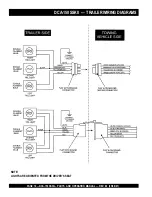
Страница 18: ...PAGE 18 DCA 150SSKII PARTS AND OPERATION MANUAL REV 2 05 08 01 NOTE LIGHTS ARE ORIENTED FROMTHE DRIVER S SEAT DCA 150SSKII TRAILERWIRING DIAGRAMS ...

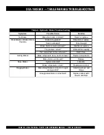
Страница 19: ... r B k a e W e d i S e n O s g n i n i l r o s t e n g a m n o l i o r o e s a e r G e c a l p e r r o n a e l C d e d o r r o c s n o i t c e n n o C e s u a c t c e r r o c d n a n a e l C n o i s o r r o c f o d e v o o r g r o d e r o c s s m u r d e k a r B e c a l p e r r o e n i h c a M d e z i n o r h c n y s s e k a r B t c e r r o C s e k a r B g n i k c o L n e k o r b r o t n e b e s o...

Страница 20: ... y l l a u q e s e r i t l l a e t a l f n I e l x a e m a s e h t n o d e h c t a m n u s e r i T s e r i t h c t a M s e k a r B g n i k c o L n e k o r b r o t n e b e s o o l s t n e n o p m o c e k a r B s t n e n o p m o c e c a l p e R d n u o r f o t u o s m u r d e k a r B e c a l p e R s e k a r B y s i o N d e t a c i r b u l m e t s y S e t a c i r b u L t c e r r o c s t n e n o p m o...

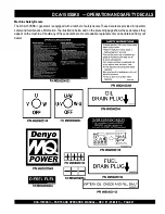
Страница 21: ... a number of safety decals These decals are provided for operator safety and maintenance information The illustration below and on the preceding page shows these decals as they appear on the machine Should any of these decals become unreadable replacements can be obtained from your dealer DCA 150SSKII OPERATION AND SAFETY DECALS ...

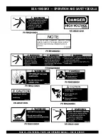
Страница 22: ...PAGE 22 DCA 150SSKII PARTS AND OPERATION MANUAL REV 2 05 08 01 DCA 150SSKII OPERATION AND SAFETY DECALS ...

Страница 23: ... e w o P C A x u A z H 0 6 e s a h P e l g n i S e g a t l o V V 0 2 1 t u p t u O 2 x W K 4 2 W K 8 4 s n o i t a c i f i c e p S e n i g n E l e d o M 2 E 8 0 1 D 6 S U S T A M O K e p y T d e g r a h c o b r u t n o i t c e j n i t c e r i d d e l o o c r e t a w e l c y c 4 s r e d n i l y C f o o N s r e d n i l y c 6 e k o r t S x e r o B m m 0 3 1 x m m 8 0 1 n i 1 1 5 x n i 5 2 4 t u p t u...

Страница 24: ...owing Three 240 139V output receptacles 50 amp Two 120V input receptacles 20 amp 3 Load Circuit Breakers 265V 65 amps 2 Load GFCI Circuit Breakers 265V 20amps Control Box The Control Box is provided with the following Main Circuit Breaker 400 amps Over Current Relay Microprocessor Controlled Alarm System The DCA 150SSKII generator is equipped with various alarms and LED status indicators These ala...

Страница 25: ...DCA 150SSKII PARTS AND OPERATION MANUAL REV 1 05 08 01 PAGE 25 NOTE PAGE ...

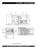
Страница 26: ...PAGE 26 DCA 150SSKII PARTS AND OPERATION MANUAL REV 2 05 08 01 DCA 150SSKII MAJOR COMPONENTS Figure 6 Major Components ...

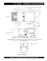
Страница 27: ...DCA 150SSKII PARTS AND OPERATION MANUAL REV 1 05 08 01 PAGE 27 DCA 150SSKII DIMENSIONS TOP SIDE AND REAR Figure 7 Dimensions ...

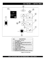
Страница 28: ...PAGE 28 DCA 150SSKII PARTS AND OPERATION MANUAL REV 2 05 08 01 DCA 150SSKII CONTROL PANEL Figure 8 Control Panel ...

Страница 29: ...conds before disengaging If the engine does not engage start by the third attempt the engine will be shut down by the MPEC s Over Crank Protection mode Iftheengineengagesataspeed RPM s that is not safe the MPEC will shut down the engine by initializing the Over Speed Protection mode Also the MPEC will shut down the generator in the event of low oil pressure high coolant temperature low coolant lev...

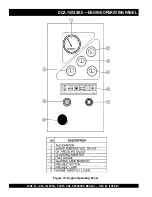
Страница 30: ...PAGE 30 DCA 150SSKII PARTS AND OPERATION MANUAL REV 2 05 08 01 DCA 150SSKII ENGINE OPERATING PANEL Figure 10 Engine Operating Panel ...

Страница 31: ...he pre heat lamp is lit ON 9 Throttle Handle This handle controls the speed of the engine low or high 7 Pre Heat Lamp Indicates that the glow plugs of the diesel engine are hot and the engine is ready to be started A Overheat Lamp This lamp goes ON when the cooling water temperature rises abnormally If the lamp goes ON during normal operation of the generator the emergency shut down device will st...

Страница 32: ... 120Volt Recetacle Two GFCI Duplex Nema 5 20R 120V 20 Amp recepacle is provided on the output terminal This receptacle can be used anytime the generator is in operation The receptacle is controlled by the circuit breaker located on the control panel Pressing the reset button resets the receptacle after being tripped Pressing the Test Button See Figure 12 in the center of this receptacle will check...

Страница 33: ...DCA 150SSKII PARTS AND OPERATION MANUAL REV 1 05 08 01 PAGE 33 Legs O and Ground are considered Bonded Grounds NOTE FIGURE 14 Output Terminal Panel DCA 150SSKII OUTPUTTERMINAL PANEL OVERVIEW ...

Страница 34: ...ng To lock the Voltage Selector Switch press in the red button located on the Voltage Selector Switch and use a pad lock to hold it into this position Over Current Relay An over current relay is connected to the circuit breaker In an over current situation both the circuit breaker and the over current relay may trip If the circuit breaker can not be reset the reset button on the over current relay...

Страница 35: ...r switch to the W U position and the AC ammeter Change over Switch to the U or W position to read the output on the selected leg FIGURE 15 Voltage Selector Switch 240 120V Single Phase Position FIGURE 16 AC Voltmeter Change over switch Reading the W U leg on the outputerminal panel FIGURE 19 ACAmmeter Amp reading on U lug FIGURE 18 AC Ammeter Change over Switch Reading the U leg on the output term...

Страница 36: ...e Hookup The output terminal panel when suppling three phase 240 volts will provide one circuit available at 361 amps with any twowiresplustheground SeeFigure23below Thevoltage selector switch must be set at the three phase 480 277V position See figure 22 below The output terminal panel when suppling 3 phase 480 volts will provide one circuit available at 180 amps available with all three wires pl...

Страница 37: ...ng up the hard wires to the lugs as shown in figure 27 below 480V will be the voltage with the Voltage Regulator Knob turned toward maximum 440 volt will be reached when the Voltage Regulator Knob is turned down and 416 volt when the Voltage Regulator Knob is toward the lowest setting See Figure 25 Single Phase 277V 254V or 240V The following connection with the voltage selector switch locked into...

Страница 38: ...ing up the hard wires to the lugs as shown in figure 32 below 240V will be the voltage with the Voltage Regulator Knob turned toward maximum 220 volt will be reached when the Voltage Regulator Knob is turned down and 208 volt when the Voltage Regulator Knob is toward the lowest setting See Figure 30 Single Phase 139V 127V or 120V The following connection with the voltage selector switch locked int...

Страница 39: ... shown in figure 36 below use the Voltage Regulator Knob to fine tune to 240V See Figure 35 Single Phase 120 Volt The following connection with the voltage selector switch locked into the single phase 240 120V position See Figure 34 will offer SINGLE PHASE power at 120V After hooking up the hard wires to the lugs as shown in figure 37 below use the Voltage Regulator Knob to fine tune to 120V See F...

Страница 40: ...xcessive back pressure which will cause the engine to heat excessively and possibly burn the valves DO NOT cover ventilation areas on the enclosure covering the ventilation grids will cause the engine to over heat CAUTION An electric shock is apt to happen when vibrators are used Pay close attention to handling when operating vibrators and always use rubber boots and gloves to insulate the body fr...

Страница 41: ...KII PARTS AND OPERATION MANUAL REV 1 05 08 01 PAGE 41 Figure 38 Typical Generator Grounding Application DCA 150SSKII INSTALLATION CAUTION Always check Local State and Federal laws before grounding generator set ...

Страница 42: ...ole 20 amp GFCI circuit breakers are provided to protect the GFCI receptaclesfromoverload Three50amploadcircuitbreakers have also been provided to protect the load side of the generator from overload Make sure to switch ALL circuit breakers to the OFF position prior to starting the engine DCA 150SSKII PRE SETUP n o i t a r e p O e s a h P e l g n i S z H 0 6 n o i t c e l e S e l b a C 1 1 e l b a...

Страница 43: ...e 39 Engine Oil Dipstick When checking the engine oil be sure to check if the oil is clean and viscous If the oil is not clean drain the oil by removingtheoildrainplug andrefillwiththespecifiedamount of oil as outlined in the Komatsu Engine Owner s Manual l i O r o t o M d e d n e m m o c e R 2 1 e l b a T e r u t a r e p m e T e g n a R l i O e p y T F 3 2 F 4 0 1 C 5 C 0 4 0 3 E A S F 5 F 3 2 C ...

Страница 44: ...tor cap until the unit has completely cooled Battery This unit is of negative ground DO NOT connect in reverse Always maintain battery fluid level between the specified marks Battery life will be shortened if the fluid level is not properly maintained Add only distilled water when replenishment is necessary The battery is sufficiently charged if the specific gravity of the battery fluid is 1 28 at...

Страница 45: ... of grease around both battery terminals This will ensure a good connection and will help prevent corrosion around the battery terminals CAUTION Inadequatebatteryconnectionsmaycause poor starting of the generator and create other malfunctions Wiring Inspect the entire generator for bad or worn electrical wiring or connections If any wiring or connections are exposed insulation missing replace wiri...

Страница 46: ...ctric drill or other power tools pay close attention to the required starting current capacity When connecting ordinary power tools a capacity of up to the generating set s rated output kW multiplied by 0 8 can be used d a o L y B r o t c a F r e w o P 5 1 e l b a T d a o L f O e p y T r o t c a F r e w o P n o i t c u d n i e s a h p e l g n i S s r o t o m 5 7 0 4 0 s r e t a e h c i r t c e l E...

Страница 47: ...ing Generator and Control Panel CAUTION 1 Be sure to disconnect the electrical load and switch the main load and G F C I circuit breakers Figure 42 to the OFF position prior to starting the engine NEVER start the engine with the main GFCI or load circuit breakers in the ON position The engine s exhaust contains harmful emissions ALWAYSventilate the exhaust when operating inside tunnels excavations...

Страница 48: ...own Observethattheenginebegins to crank 5 WhenstartingthegeneratorinCOLDweatherconditions press and hold the engine preheat button Figure 46 until the pre heat lamp Figure 47 is lit ON Figure 46 Engine Pre Heat Button Figure 47 Engine Pre Heat Lamp 8 If the unit has an ignition switch Figure 50 turn the key to the right until the engine starts Then release the key to Run Figure 50 Ignition Switch ...

Страница 49: ... conditions the oil pressure should be approximately 25 psi 15 The coolant temperature gauge Figure 58 will indicate the coolant temperature Under normal operating conditions the coolant temperature should be between 105 and 215 degrees fahrenheit Green Zone WATER TEMP Figure 58 Coolant Temperature Gauge A 0 40 60 75 20 Figure 56 Ammeter No Load Figure 57 Oil Pressure Gauge Figure 53 Frequency Met...

Страница 50: ...steps 1 through 6 page 47 48 as outlined in the manual starting procedure 2 Place the Off Manual Auto switch Figure 62 in the AUTO position up Observe that the engine begins to crank 19 Look at the generator s ammeter Figure 61 and verify that it reads the anticipated amount of current with respect to the load Remember the ammeter will only display a current reading if the load is in use 20 The ge...

Страница 51: ...unning Status LED OFF 6 Verify that the Engine Running status LED Figure 66 on the Microprocessor Engine Control Module MPEC display is OFF not lit 7 Ifthegeneratorisequippedwithanignitionswitch Figure 67 turn the key to the left to the OFF positionturn off the engine 5 Place the Off Manual Auto Switch Figure 65 in the OFF RESET position 4 Let the engine cool by running it for 3 5 minutes with no ...

Страница 52: ... fuel or oil leaks Engine Side Fuel Oil and Coolant Refer to the Engine Instruction Manual Air Cleaner Every50hours Removeaircleanerelementandcleanheavy duty paper element with kerosene or foam element with liquid detergent and hot water Wrap foam element in a cloth and squeeze dry For heavy duty paper element wipe excess kerosene with towel Fuel Addition Add diesel fuel the grade may vary accordi...

Страница 53: ...X r e t l i F r i A n a e l C X k n a T l e u F f o m o t t o B n i a r D X e d i s t u O d n a e d i s n I t i n U n a e l C X r e t l i F l e u F e g n a h C 2 X t n a l o o C k c e h C d n a r o t a i d a R n a e l C l e v e L n o i t c e t o r P X t n e m e l E r e t l i F r i A e c a l p e R X r o t s i s e R n o i s o r r o C e g n a h C X s p m a l C d n a s e s o H l l a k c e h C X k n a ...

Страница 54: ... l e u f d e i f i c e p s e h t e s U e n a t e c w o l h t i w l e u F r e b m u n l e u f d e i f i c e p s e h t e s U e s o o l o t e u d k a e l l e u F t u n g n i n i a t e r e p i p n o i t c e j n i t u n n e t h g i T g n i m i t n o i t c e j n i t c e r r o c n I t s u j d A n r o w t f a h s m a c l e u F e c a l p e R d e g g o l c e l z z o n n o i t c e j n I e l z z o n n o i t c...

Страница 55: ... i f i c e p s e h t o t e c u d e R n r o w r e n i l d n a g n i r n o t s i P k c u t s r o e c a l p e r r o r i a p e R g n i m i t n o i t c e j n i t c e r r o c n I t s u j d A n o i s s e r p m o c t n e i c i f e D e c n a r a e l c p o t t s u j d A y a r g k r a d r o k c a l b r e h t i E d e v r e s b o s i s a g t s u a h x e d a o l r e v O d a o l e h t n e s s e L d e s u l e u f...

Страница 56: ...r i w r i a p e r d n a k c e h C o n d n a s e s i r d e e p s e n i g n E C A n t n e s e r p s i e g a e t l o v e c r u o s r e w o p C A n i t n e s e r p e g a t l o v o N e c r u o s r e w o p 1 E R r e i f i t c e r e c a l p e R r o t o r e v i t c e f e D r o t o r e c a l p e R r e t e m t l o v e v i t c e f e D r e t e m t l o v e c a l p e R g n i r i w d e t c e n n o c s i D g n i ...

Страница 57: ...o t a i d a r r i a p e r n a e l C n e p o s r o o D s r o o d e s o l C g n i k a e l t s u a h x E t r a p y t l u a f r o s t e k s a g r i a p e r e c a l p e R d e d a o l r e v o g n i e b r o t a r e n e G d a o l e c u d e r k c e h C e r u l i a f t a t s o m r e h T t a t s o m r e h t e c a l p e R d e k c o l b e k a t n i r i A s e k a t n i r i a l l a r a e l C e r u l i a f h c t ...

Страница 58: ...tems Found In the Remarks Column Serial Numbers Where indicated this indicates a serial number range inclusive where a particular part is used Model Number Where indicated this shows that the corresponding part is utilized only with this specific model number or model number variant Items Found In the Items Number Column All parts with same symbol in the number column or belong to the same assembl...

Страница 59: ... RECEPTACLE 530 EM 1 0601812565 RECTIFIER 3 0602041147 OIL FILTER CARTRIDGE 1 0810105004 FUEL TANK CAP 3 0602042146 FUEL FILTER CARTDIDGE 3 0602046338 ELEMENT AIR INNER 1 6008155390 STARTER SWITCH 3 615 KEY IGNITION 1 0602123087 WATERTEMPERATURE GAUGE 1 0602122037 OIL PRESSURE GAUGE 1 0602122251 OIL SHUT DOWN SENDING UNIT 1 0602123250 WATER TEMPERATURE SENDING UNIT 3 0601822034 RECEPTACLE CS 6369 ...

Страница 60: ...PAGE 60 DCA 150SSKII PARTS AND OPERATION MANUAL REV 2 05 08 01 GENERATOR ASSY DCA 150SSKII GENERATOR ASSY ...

Страница 61: ...OCKWASHER 4 1 16 0601000209 BALANCING WEIGHT KIT 1 1 17 0071906312 BEARING 1 2 8151340213 STATOR ASSY 1 3 0845041804 GROMMET 2 4 8131315102 END BRACKET 1 5 8101350013 FIELD ASSY EXCITER 1 6 0012110060 HEX HEAD BOLT 4 7 0042610000 LOCKWASHER 4 8 031110160 PLAINWASHER 4 REPLACES 0041210000 9 0010112035 HEX HEAD BOLT 6 10 0040012000 LOCKWASHER 6 11 031112230 PLAINWASHER 6 REPLACES 0041212000 12 81313...

Страница 62: ...PAGE 62 DCA 150SSKII PARTS AND OPERATION MANUAL REV 2 05 08 01 DCA 150SSKII CONTROL BOX ASSY CONTROL BOX ASSY ...

Страница 63: ...CES 0602200446 11 0017106016 HEX HEAD BOLT 4 12 0601823860 RELAY UNIT 2 MSA9013 13 0027104010 MACHINE SCREW 4 14 0601823706 RELAY 1 HE1A DC24V 15 0027104010 MACHINE SCREW 2 16 0601823861 STOP UNIT 1 MSA9014 17 0027104010 MACHINE SCREW 2 18 6008152970 GLOW RELAY 1 REPLACES 0602201227 19 0017106016 HEX HEAD BOLT 2 20 0601824542 RELAY 1 HH62S DC24V 21 0227103010 MACHINE SCREW 2 22 0602201911 UNIT BAT...

Страница 64: ...PAGE 64 DCA 150SSKII PARTS AND OPERATION MANUAL REV 2 05 08 01 DCA 150SSKII CONTROL BOX ASSY CONTROL BOX ASSY ...

Страница 65: ... RA20A2SE102BJ 2W 1K OHM 40 0601840121 KNOB 1 41 0601810161 PANEL LIGHT 1 V325070 0601810214 BULB 1 42 0030004000 HEX NUT 2 REPLACES 0207004000 43 0601830710 SWITCH PANEL LIGHT 1 44 C9221100004 HEX HEAD BOLT 2 0040008000 LOCKWASHER 2 031108160 PLAINWASHER 2 REPLACES 0041208000 0080100007 SNAP RING 2 45 3871824004 STOPPER CONTROL PANEL 1 46 952404470 PLAINWASHER 1 REPLACES 0041206000 47 505015300 S...

Страница 66: ...PAGE 66 DCA 150SSKII PARTS AND OPERATION MANUAL REV 2 05 08 01 DCA 150SSKII ENGINE RADIATOR ASSY ENGINE RADIATOR ASSY ...

Страница 67: ...LACES 0041212000 7 C0311100004 BRACKET RADIATOR 2 8 0017110025 HEX HEAD BOLT 6 9 6221619320 RADIATOR HOSE 1 REPLACES 0602014543 10 6221619330 RADIATOR HOSE 1 REPLACES 0602014425 11 0726020971 RADIATOR HOSE 1 REPLACES 0602014544 12 0728100909 HOSE BAND 1 REPLACES 0602014056 13 0728100809 HOSE BAND 2 REPLACES 0602014067 14 0728101029 HOSE BAND 1 REPLACES 0602014350 15 0728100197 HOSE BAND 2 REPLACES...

Страница 68: ...PAGE 68 DCA 150SSKII PARTS AND OPERATION MANUAL REV 2 05 08 01 DCA 150SSKII ENGINE RADIATOR ASSY ENGINE RADIATOR ASSY ...

Страница 69: ...1003 33 0802010900 CAP RESERVE TANK 1 REPLACES 0602010900 34 8302082103 BRACKET RESERVE TANK 1 35 0021108020 MACHINE SCREW 2 36 020108060 HEX NUT 2 REPLACES 0207008000 37 0199601200 HOSE 1 38 0193601200 HOSE 1 39 0605515013 HOSE BAND 3 40 0193600450 HOSE 1 41 0193600800 HOSE 1 42 0268200900 HOSE 1 43 0605515132 HOSE BAND 2 44 8302256104 CLAMPER ROD 1 45 8152256104 CLAMPER ROD 1 46 012210020 HEX HE...

Страница 70: ...PAGE 70 DCA 150SSKII PARTS AND OPERATION MANUAL REV 2 05 08 01 DCA 150SSKII ENGINE OPERATING PANEL ASSY ENGINE OPERATING PANEL ASSY ...

Страница 71: ...MACHINE SCREW 2 5 0021806020 MACHINE SCREW 2 6 0021806050 MACHINE SCREW 2 7 0602120129 CABLE TACHOMETER 1 0578909990 8 0602122251 UNIT OIL PRESSURE 1 0716000760 9 0602123250 UNIT WATERTEMPERATURE 1 0715000331 10 8132142004 SLIDE LEVER 1 11 0601840190 KNOB 1 REPLACES 0805012904 12 0036003000 HEX NUT 1 13 7452140504 BRACKET 1 14 0030008000 HEX NUT 2 15 0605010503 SNAP PIN 1 16 6008155390 STARTER SWI...

Страница 72: ...PAGE 72 DCA 150SSKII PARTS AND OPERATION MANUAL REV 2 05 08 01 DCA 150SSKII ENGINE OPERATING PANEL ASSY ENGINE OPERATING PANEL ASSY ...

Страница 73: ...BER COVER 1 40 0845032004 SET FRAME RUBBER COVER 1 41 011008020 HEX HEAD BOLT 4 REPLACES 0017108020 42 0601812597 RECEPTACLE 2 530EM REPLACES 0601812598 43 0601811034 RECEPTACLE 3 CS6369 REPLACES 0601812565 44 0021304015 MACHINE SCREW 10 REPLACES 0027104015 0030004000 HEX NUT 10 031104080 PLAINWASHER 10 REPLACES 0041204000 45 06018053136 CIRCUIT BREAKER 2 KM 51265V20A 46 0601805840 CIRCUIT BREAKER...

Страница 74: ...PAGE 74 DCA 150SSKII PARTS AND OPERATION MANUAL REV 2 05 08 01 DCA 150SSKII BATTERY ASSY BATTERY ASSY ...

Страница 75: ...ER 4 7 0041208000 PLAINWASHER 4 REPLACES 0041208000 8 0602220203 BATTERY SENSOR 1 9 C0347500004 BATTERY CABLE 1 10 8302265304 BATTERY CABLE 1 11 8302265504 BATTERY CABLE 1 12 C0347200104 EARTH CABLE 1 13 012010030 HEX HEAD BOLT 4 REPLACES 0010010030 14 020310080 HEX NUT 4 REPLACES 0030010000 15 012212025 HEX HEAD BOLT 1 REPLACES 0010012025 0040012000 LOCKWASHER 1 031112230 PLAINWASHER 1 REPLACES 0...

Страница 76: ...PAGE 76 DCA 150SSKII PARTS AND OPERATION MANUAL REV 2 05 08 01 MUFFLER ASSY DCA 150SSKII MUFFLER ASSY ...

Страница 77: ...025 HEX HEAD BOLT 4 3 C0334000003 EXHAUST PIPE 1 4 6150115751 GASKET 1 REPLACES 0602320142 5 0012112045 HEX HEAD BOLT 4 0030012000 HEX NUT 4 031112230 PLAINWASHER 8 REPLACES 0041212000 6 0010112050 HEX HEAD BOLT 4 0030012000 HEX NUT 4 031112230 PLAINWASHER 8 REPLACES 0041212000 7 8252354004 COVER 2 8 C0334200104 SHEET 2 9 011008020 HEX HEAD BOLT 4 REPLACES 0017108020 ...

Страница 78: ...PAGE 78 DCA 150SSKII PARTS AND OPERATION MANUAL REV 2 05 08 01 FUEL TANK ASSY DCA 150SSKII FUELTANK ASSY ...

Страница 79: ...0257700385 HOSE FUEL GAUGE 1 2 8135523304 TANK BAND 2 3 0805003414 PAD TANK BAND 4 4 011008020 HEX HEAD BOLT 2 REPLACES 0017108020 5 020108060 HEX NUT 2 REPLACES 0037908000 6 0222100320 TANK SHEET 4 7 0845047504 DRAIN JOINT 1 8 0802011104 PLUG 1 9 0150000018 O RING 1 10 0191301100 SUCTION HOSE 1 11 0191301200 RETURN HOSE 1 12 0191001750 RETURN HOSE 1 13 0605515014 HOSE BAND 4 14 0605515013 HOSE BA...

Страница 80: ...E FOLLOWING DIGITS AFTER THE PART NUMBER WHEN ORDERING ANY PAINTED PANEL TO INDICATE COLOR OF UNIT 1 ORANGE 2 WHITE 3 SPECTRUM GRAY 4 SUNBELT GREEN 5 BLACK 6 CATERPILLARYELLOW 7 CATO GOLD 8 RED THE SERIAL NUMBER MAY BE REQUIRED DCA 150SSKII ENCLOSURE ASSY ENCLOSURE ASSY ...

Страница 81: ...110 HEX NUT 4 REPLACES 0030014000 030214350 LOCKWASHER 4 REPLACES 0040014000 031114260 PLAINWASHER 4 REPLACES 0041214000 14 0010120045 HEX HEAD BOLT 4 0030020000 HEX NUT 4 0040020000 LOCKWASHER 4 0041220000 PLAINWASHER 4 15 C0444000802 REAR FRAME 1 8305940104 LINING 1 16 0017110025 HEX HEAD BOLT 4 17 8155155403 COVER REAR FRAME 1 8155944104 LINING 1 18 011008020 HEX HEAD BOLT 14 REPLACES 001710802...

Страница 82: ...E FOLLOWING DIGITS AFTER THE PART NUMBER WHEN ORDERING ANY PAINTED PANEL TO INDICATE COLOR OF UNIT 1 ORANGE 2 WHITE 3 SPECTRUM GRAY 4 SUNBELT GREEN 5 BLACK 6 CATERPILLARYELLOW 7 CATO GOLD 8 RED THE SERIAL NUMBER MAY BE REQUIRED DCA 150SSKII ENCLOSURE ASSY ENCLOSURE ASSY ...

Страница 83: ...2 C0454202102 SPLASHER PANEL 1 43 0017108055 HEX HEAD BOLT 4 44 C0454002203 SIDE DOOR 1 C0494403204 LINING 1 45 C0454002303 SIDE DOOR 1 C0494403304 LINING 1 46 C0454002403 SIDE DOOR 1 C0494403404 LINING 1 47 C0454002503 SIDE DOOR 1 C0494403504 LINING 1 48 8135176104 DUCT 2 8135976104 LINING 1 49 8135176004 DUCT 1 8135976304 LINING 1 50 020108060 HEX NUT 21 REPLACES 0207008000 51 B9114000002 DOORHA...

Страница 84: ...PAGE 84 DCA 150SSKII PARTS AND OPERATION MANUAL REV 2 05 08 01 DCA 150SSKII RUBBER SEALS ASSY RUBBER SEALS ASSY ...

Страница 85: ...ASSY NO PART NO PART NAME QTY REMARKS 1 0228901080 RUBBER SEAL 6 2 0228900840 RUBBER SEAL 4 3 0228900730 RUBBER SEAL 2 4 0228901080 RUBBER SEAL 4 5 0229201200 RUBBER SEAL 4 6 0228800650 RUBBER SEAL 2 7 0228801045 RUBBER SEAL 2 8 0229201190 RUBBER SEAL 1 9 0228100320 RUBBER SEAL 2 10 0228100540 RUBBER SEAL 2 ...

Страница 86: ...PAGE 86 DCA 150SSKII PARTS AND OPERATION MANUAL REV 2 05 08 01 DCA 150SSKII NAME PLATE AND DECALS NAME PLATE AND DECALS ...

Страница 87: ... 150 1 C06110350 2 12 C251000004 DECAL SAFETY INSTRUCTIONS 1 C25100000 ENGINE RADIATOR GROUP 3 1 6360610304 DECAL WATER 1 S 1880 3 2 6360620204 DECAL OIL DRAIN PLUG 1 S 1885 3 3 B9504000404 DECAL WARNING 2 B90400040 3 4 B9504100104 DECAL WARNING 1 B90410010 ENGINE OPERATING PANEL GROUP 4 1 0840625004 DECAL PREHEAT LAMP 1 S 3036 4 2 0840625104 DECAL STARTER SWITCH 1 S 3037 4 3 0840625204 DECAL SPEE...

Страница 88: ...PAGE 88 DCA 150SSKII PARTS AND OPERATION MANUAL REV 2 05 08 01 DCA 150SSKII NAME PLATE AND DECALS NAME PLATE AND DECALS ...

Страница 89: ... GROUP 8 1 1320620904 DECAL DIESEL FUEL 1 S 1756 8 2 6360620004 DECAL FUEL DRAIN PLUG 1 S 1883 8 3 B9504500004 DECAL WARNING 1 B 90450000 ENCLOSURE GROUP 9 1 1320610603 DECAL WATER OIL 1 S 1760 9 2 1320621504 DECAL SUPPORT HOOK 2 S 2257 9 3 0840625902 DECAL MQ 1 S 3057 9 4 B9504000304 DECAL CAUTION 1 B90400030 9 5 C0561100402 STRIPE 1 9 6 C0561101203 STRIPE 1 9 7 C0561100204 STRIPE 2 9 8 C05611006...

Страница 90: ...t be liable here under for damagesinexcessofthepurchasepriceofthe item with respect to which damages are claimed and in no event shall Multiquip be liable for loss of profit or good will or for any other special consequential or incidental damages LIMITATIONOFWARRANTIES Nowarranties expressorimplied aremade in connection with the sale of parts or trade accessories nor as to any engine not manufact...

Страница 91: ...DCA 150SSKII PARTS AND OPERATION MANUAL REV 1 05 08 01 PAGE 91 NOTE PAGE ...

Страница 92: ...a Boise Dallas Houston Newark Quebec Canada Manchester UK RioDeJaniero BR Guadalajara MX HERE S HOW TO GET HELP PLEASE HAVE THE MODEL AND SERIAL NUMBER ON HANDWHEN CALLING PARTS DEPARTMENT 800 427 1244 or 310 537 3700 FAX 800 672 7877 or 310 637 3284 SERVICE DEPARTMENT 800 835 2551 or 310 537 3700 FAX 310 638 8046 WARRANTY DEPARTMENT 800 835 2551 or 310 537 3700 FAX 310 638 8046 MAIN 800 421 1244 ...

Отзывы: