background image

ATD 50 Actuator

®

 Operating Instructions

Page 13

3811 N. Holton Street • Milwaukee, WI • 53212 •USA • Phone • 414-906-4000 • Fax 414-906-4100 • www.MPCovers.com

7  Error Diagnosis

There are 10 error conditions that can be detected by installing LED’s to specific  “B
TERMINAL STRIP” outputs inside the ATD 50 Actuator

®

.

The errors are indicated

according to the following code:

Software Error Number

2

Calibration run is taking place.  Wait until door is closed for error to clear

3

Main power failure.

9

Microprocessor error or drive type not specified.  Contact Factory.

10

Emergency stop activated.

11

Motor overheated.  Allow motor to cool for reset or Contact Factory.

12

Power module faulty or low mains voltage.

13

No movement is detected from the door.  Possibly the encoder, cable,
motor, or belt is defective.  Door is possibly blocked.

16

Door is in reversing mode because it has encountered an obstruction.
Wait until door is closed.

29

External reversing on closing.

30

External reversing on opening.

NOTE:

  The software errors can also be detected using the SERsoft  programming

software.  The errors are displayed in the Error Window in the Diagnostic Menu.

Содержание ATD ACTUATOR 50 ATD-313186 Operating and

Страница 1: ...Installation Instructions Milwaukee Protective Covers 2300 South Calhoun Road New Berlin WI 53151 Phone 414 906 4000 Fax 414 906 4100 1998 Milwaukee Protective Covers V2 0 www MPCovers com Automatic Door Drive Model 50 ATD 313186 ...

Страница 2: ...quirements 5 2 3 General Information and MPC Liability 5 3 Theory of Operation 6 4 Design Information 7 4 1 Mechanical 7 4 1 1 The Door 7 4 1 2 Installation Position 7 4 1 3 Installation 8 4 2 Electrical 9 4 2 1 Main Power Connection 9 4 2 2 Control Connection 10 5 Start up Procedure 10 5 1 Preparation 10 5 2 Start up 11 6 Check List for Functional Tests 11 7 Error Diagnosis 13 8 Hardware Error Di...

Страница 3: ...2 USA Phone 414 906 4000 Fax 414 906 4100 www MPCovers com 11 Operation 19 11 1 Calibration Run 19 11 2 Door Movements 20 11 3 Reversing Motion 20 12 Memory and System Layout 21 13 Technical Data 22 14 Electrical Wiring Diagram 24 15 Physical Dimensions 25 16 Trouble Shooting Guide 26 ...

Страница 4: ...Damage to the unit and personal injury may result from not following these instructions Keep fingers away from all moving parts Be especially careful to install guards or shield to protect personnel from the moving drive belt and pulleys Be sure the electrical power is disconnected and locked out when working on the ATD 50 Actuator Install the electrical cables and power only after the mechanical ...

Страница 5: ...t decide if additional positive latches are required to insure proper machine safety Use the ATD 50 Actuator system only when it is operating properly and as designed Any problems or malfunctions should be repaired immediately The safety systems of the ATD 50 Actuator unit depend upon correct operation 2 2 Design and Installation Personnel Requirements The design and installation of the guard door...

Страница 6: ...lwaukee Protective Covers specifically declines any responsibility for damage or injury resulting from unauthorized changes to the drive including software parameter changes No employee of Milwaukee Protective Covers is authorized to modify this warranty without the specific written approval of a company officer 3 Theory of Operation The ATD 50 Actuator is controlled using a built in microprocesso...

Страница 7: ...operation The door should have a consistent drag force over its complete travel The door guides should provide as low a drag resistance as possible This will insure trouble free operation and will increase the drives sensitivity to any obstructions 4 1 2 Installation Position The ATD 50 Actuator can be installed in any position and any orientation according to the specific application The drive be...

Страница 8: ... the unit and four button head cap screws on the top For installation only the four screws on the top OR the two screws on the back should be used Never loosen all 6 screws at the same time Otherwise the internal frame will be loose inside the metal housing If the internal frame is allowed to move inside the metal housing the drive shaft can be damaged by scraping against the sealing elements Unde...

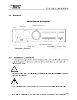
Страница 9: ...r 4 2 1 Main Power Connection The main power supply can be switched between 115 volts and 230 volts and with 50 or 60 Hz AC power There is an internal switch on the main power connection to select 115V or 230V The main power must be externally protected with a 10 amp fast blow fuse and a system disconnect Verify that the power selection switch is set to the correct voltage before start up ...

Страница 10: ...ate inputs Outputs Six 6 potential free output relays are provided Three 3 relays are wired as normally open and three 3 are wired as normally closed See page 24 5 Start up Procedure 5 1 Preparation Prepare the ATD 50 Actuator by completing the following steps Mount the drive box on a rigid base in a suitable position Install the idler pulley to a rigid base on the machine Cut the drive belt to le...

Страница 11: ...ests the door travel path must be free of obstructions The only limits to door travel should be the two end stops Test the unit according to the following steps TEST 1 POWER UP ACTION Energize the main power to the ATD 50 Actuator EXPECTED BEHAVIOR No door movement Green LED on the Control Board illuminates Door is freely moveable No errors displayed on LED at terminals D5 D9 if installed No error...

Страница 12: ...Door should open and close normally The microprocessor measures the torque and sets the internal speed and torque references These references are used as safety thresholds for detecting obstructions NOTE The safety reversing function is not active during the first two 2 open and close cycles See Sec 11 1 TEST 4 CHECK ALL FUNCTIONS ACTION Activate all connected functions and options such as CNC PLC...

Страница 13: ...ain power failure 9 Microprocessor error or drive type not specified Contact Factory 10 Emergency stop activated 11 Motor overheated Allow motor to cool for reset or Contact Factory 12 Power module faulty or low mains voltage 13 No movement is detected from the door Possibly the encoder cable motor or belt is defective Door is possibly blocked 16 Door is in reversing mode because it has encountere...

Страница 14: ...ntroller has a red and green LED light in the lower right corner The LED lights indicate the general status of the microprocessor GREEN LED The microprocessor controller is operating correctly RED LED Any of the following conditions A software error is detected The emergency stop is active E Stop Jumper connection between terminals D1 D2 is missing The motor is overheated Controller Failure ...

Страница 15: ...uns The maintained contact can be held until the errors clear In this situation the machine controller can monitor Relay 1 or 2 and maintain the inputs to A2 and A7 until the errors clear OPEN This command will move the door to the full open position Input terminal A2 Type of signal Momentary or maintained contact A2 to Ground A1 Active level Connection is normally open Close connection to activat...

Страница 16: ...nd will release the brake and allow the operator to manually move the door While this signal is present no other command will be carried out Input terminal C7 Type of signal Momentary or maintained contact C7 to Ground A1 Active level Connection is normally open Close connection to activate REVERSE CLOSING This command reverses the door movement when closing The door will reverse direction and mov...

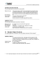
Страница 17: ...connection to activate program the position EMERGENCY STOP This command will instantly stop all door movement Reason for use To interface to your machine s E stop circuit Input terminal D1 D2 Type of signal Momentary or maintained open between D1 and D2 Active level Connection is normally closed Open connection to activate stop door movement 10 Standard Output Functions The output signals are conn...

Страница 18: ...E5 E6 Relay 3 Active level Contact is normally open Closed contact when activated DOOR POSITION OPEN This output is active when the door is in the open position 1 5 inch The output is active also when the door is manually moved to the open position Output terminal I1 I2 Relay 4 Active level Contact is normally closed Open contact when door is in the full open position DOOR IS CALIBRATED This outpu...

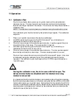
Страница 19: ...A CLOSE signal must be given to the ATD 50 Actuator by a momentary or maintained contact from A7 to Ground A1 5 The door moves slowly to the extreme closed end stop The door pushes against the end stop with full force then stops The door closed position is now set The door must contact the end stop using the ATD 50 Actuator power If the door is interrupted during the calibration cycle the calibrat...

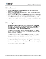
Страница 20: ...sing three variables 1 Stall Time 2 Speed and 3 Motor Torque An obstruction is assumed if 1 The door stalls for more then one second 2 The speed of travel is slower than a predetermined threshold and 3 The torque needed is greater than the reference torque If an obstruction is encountered during a CLOSE movement the door reverses direction and moves to the full open position The ATD 50 Actuator wa...

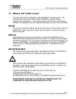
Страница 21: ...ll parameters which are entered or modified using the SERsoft programming software The more specific instructions for the ATD 50 Actuator are stored in the EEPROM The parameters and instructions stored in the EEPROM can be saved in a SERsoft programming software file Contact MPC for more information MICROPROCESSOR The microprocessor follows the general operational instructions of the EPROM while a...

Страница 22: ...tion min 4 W max 160 W Motor Nominal Speed 1600 rpm Motor Nominal Torque 9 inch lbs 1 Nm Maximum Drive Speed 443 rpm Maximum Tensile Force of Belt 30 lbs 130 N Maximum Drive Torque 32 inch lbs 3 6 Nm Absolute Maximum Opening Speed 40 inches second 1000 mm sec Absolute maximum Closing Speed 40 inches second 1000 mm sec Maximum Permissible Door Weight 265 lb 120 kg total weight of all leafs Weight o...

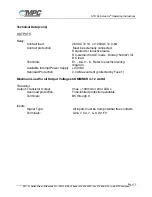
Страница 23: ...s RC element for AC loads Diode 1N4007 for DC load Terminals E1 6 I1 6 Refer to electrical wiring diagram Available Internal Power Supply 24VDC Overload Protection 2 0A Max current protected by Fuse 1 Maximum Load for all Output Voltages COMBINED is 12 watts Transistor Output Transistor Output Imax 100mA for error LEDs Overload protection Time limited protection available Terminals B5 through 9 In...

Страница 24: ...ATD 50 Actuator Operating Instructions Page 24 3811 N Holton Street Milwaukee WI 53212 USA Phone 414 906 4000 Fax 414 906 4100 www MPCovers com 14 Electrical Wiring Diagram ...

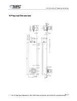
Страница 25: ...ATD 50 Actuator Operating Instructions Page 25 3811 N Holton Street Milwaukee WI 53212 USA Phone 414 906 4000 Fax 414 906 4100 www MPCovers com 15 Physical Dimensions ...

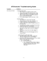
Страница 26: ...ltage is present on the signal wires x The signal wire is properly connected to the terminal x Verify that the wires are not damaged x Is the ribbon cable from the input signal board to the ATD control module ATD 50 and 101 plugged in properly x Are the quick connect wire terminals plugged in properly x Are the quick connect terminals plugged into the correct location Control Module Functioning Pr...

Страница 27: ... Connect SERsoft and establish ON LINE Connection Make sure you are using correct SERsoft version V1 2 for ATD 100 and V1 5 for ATD 50 and 101 x Check Diagnostics Screen for any errors x Verify the correct Actuator Type is programmed in the Basic Functions screen x ATD 50 Should display MxP 50 ATD 50 x ATD 100 Should display MxP 100 ATD 100 x ATD 101 Should display MxP 101 ATD 101 See Reprogrammin...

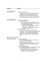
Страница 28: ... Basic Functions Screen 2 Is this an ATD 101 x Increase Braking Distance to at least 400mm x Possible fix Turn off only the Speed Lagging Option in the Motion Control Reversing Options Menu x Possible fix Turn off only the Force Reversing Option in the Motion Control Reversing Options Menu Door moves very short distance and stops Error 1301 Door Opening too small 1 Mechanically Related x Is the do...

Страница 29: ... Runs Slow against end stop 1 Open End Stop Tolerance in Motion Control set to a small distance or zero 2 Homing in Speed set too high slamming or too low door moves slowly 3 Homing in Distance set too long door too slow 4 Homing in Distance set too short door slams 5 Braking Distance too short 6 Opening Dampening set to Hard 7 For ATD 101 ONLY In opening Direction enter the following into DIRCOM ...

Отзывы: