Moxa Technologies ToughNet TN-5524-8PoE Скачать руководство пользователя страница 4

- 4 - 

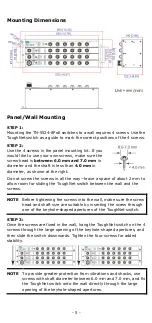
TN-5524-8PoE Panel Layouts 


1.


Screw holes for panel mounting kit 

2.


Console port 

3.


Grounding screw 

4.


Relay output port 

5.


Power input voltage range indication 

6.


Power input port (male 6-pin shielded M23 connector) 

7.


PWR1 LED: for power input 1 

8.


PWR2 LED: for power input 2 

9.


FAULT LED 

10.


MSTR/HEAD LED: for ring master or chain head 

11.


CPLR/TAIL LED: for ring coupler or chain tail 

12.


TP port’s 10/100 Mbps LED 

13.


10/100BaseT(X) port (female 4-pin shielded M12 connector with D 
coding) 

14.


10/100BaseT(X) PoE port (female 4-pin shielded M12 connector 
with D coding) 

15.


LED for PoE port 

Содержание ToughNet TN-5524-8PoE

Страница 1: ...ort Moxa Americas Toll free 1 888 669 2872 Tel 1 714 528 6777 Fax 1 714 528 6778 Moxa China Shanghai office Toll free 800 820 5036 Tel 86 21 5258 9955 Fax 86 21 5258 5505 Moxa Europe Tel 49 89 3 70 03...

Страница 2: ...ckage Checklist Your ToughNet TN 5524 8PoE switch is shipped with the following items If any of these items is missing or damaged contact your customer service representative for assistance 1 Moxa Tou...

Страница 3: ...ating temperature range for T models IP40 rugged high strength housing Panel mounting mounting installation capability This product is suitable for rolling stock railway applications as defined by the...

Страница 4: ...n shielded M23 connector 7 PWR1 LED for power input 1 8 PWR2 LED for power input 2 9 FAULT LED 10 MSTR HEAD LED for ring master or chain head 11 CPLR TAIL LED for ring coupler or chain tail 12 TP port...

Страница 5: ...sliding the ToughNet switch between the wall and the screws NOTE Before tightening the screws into the wall make sure the screw head and shaft size are suitable by inserting the screw through one of...

Страница 6: ...trical codes dictating the maximum current allowable for each wire size If the current goes above the maximum ratings the wiring could overheat causing serious damage to your equipment Be sure to read...

Страница 7: ...r input port on the TN 5524 8PoE Pinouts for the power input port on the TN 5524 8PoE Pin Description Usage 1 PWR1 Live DC Connect PWR1 Live DC to the Live terminal when using an AC power source or to...

Страница 8: ...contacts form an open circuit when a user configured event is triggered If a user configured event does not occur the fault circuit remains closed Connecting the Data Lines 10 100BaseT X Ethernet Port...

Страница 9: ...uts Pin Signal 1 Tx 2 Tx 3 Rx 6 Rx Pin Signal 1 Rx 2 Rx 3 Tx 6 Tx M12 4 pin M to M12 4 pin M Cross Over Cable Wiring M12 4 pin M to M12 4 pin M Straight Trough Cable Wiring M12 4 pin M to RJ45 8 pin C...

Страница 10: ...Chain Blinking When the TN switch is Ring Master of this Turbo Ring and the Turbo Ring is broken or it is Chain Head of this Turbo Chain and the Turbo Chain is broken OFF When the TN switch is neithe...

Страница 11: ...ity Queues 4 Max Number of Available VLANs 64 VLAN ID Range VID 1 to 4094 IGMP Groups 256 Interface Fast Ethernet Front cabling M12 connector 10 100BaseT X auto negotiation speed F H duplex mode and a...

Страница 12: ...er 2 kV Signal 2 kV IEC 61000 4 6 CS 10 V IEC 61000 4 8 Rail Traffic for panel mounting installations EN 50155 EN 50121 4 EN 45545 2 This product is suitable for rolling stock railway applications as...

Отзывы: