Moxa Technologies IKS-G6524A Скачать руководство пользователя страница 4

- 4 - 

USB Console Connection 

The IKS-G6524A/G6824A series has one USB console port (type B 
connector), located on the top panel. Use the USB cable (provided in the 
product package) to connect the IKS-G6524A/G6824A’s console port to 
your PC’s USB port and install the USB driver (available in the software CD) 
on the PC. You may then use a console terminal program, such as Moxa 
PComm Terminal Emulator, to access the IKS-G6524A/G6824A’s console 
configuration utility. 

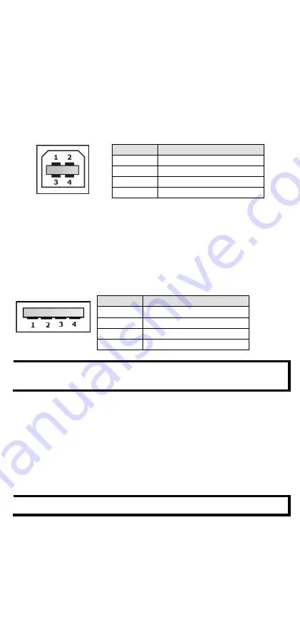
USB Console Port (Type B Connector) Pinouts 


Pin 

Description 

D– (Data -) 

VCC (+5V) 

D+ (Data+) 

GND (Ground) 


USB Storage Connection 

The IKS-G6524A/G6824A series has one USB storage port (type A 
connector) on the front panel. Use the Moxa ABC-02-USB automatic 
backup configurator to connect the IKS-G6524A/G6824A’s USB storage 
port for configuration backup, firmware upgrade, or system log file 
backup. 

USB Storage Port (Type A Connector) Pinouts 


Pin 

Description 

VCC (+5V) 

D– (Data -) 

D+ (Data+) 

GND (Ground) 


NOTE 

DO NOT pull out the ABC-02-USB automatic backup configurator 
from the USB port while writing or reading data. 


The Reset Button 

Press the Reset button for five continuous seconds to load the factory 
default settings. Use a pointed object, such as a straightened paper clip or 
toothpick, to press the Reset button. When you do so, the STATE LED will 
start to blink about once per second. Continue to press the STATE LED 
until it begins blinking more rapidly, indicating that the button has been 
pressed continuously for five seconds. You can now release the Reset 
button to load factory default settings. 

NOTE 

DO NOT power off the switch when loading default settings. 


Содержание IKS-G6524A

Страница 1: ...xa Americas Toll free 1 888 669 2872 Tel 1 714 528 6777 Fax 1 714 528 6778 Moxa China Shanghai office Toll free 800 820 5036 Tel 86 21 5258 9955 Fax 86 21 5258 5505 Moxa Europe Tel 49 89 3 70 03 99 0...

Страница 2: ...d 4 protective caps for unused ports 2 rackmount ears Quick installation guide printed Warranty card Panel Layouts 1 Model Name 2 System status LEDs 3 10 100 1000BaseT X port status LEDs 4 100 1000Bas...

Страница 3: ...pply 1 PWR1 and Power Supply 2 PWR2 The connections for PWR1 and PWR2 are located on the rear side shown below Be sure to use a standard power cord with an IEC C13 connector which is compatible with t...

Страница 4: ...backup configurator to connect the IKS G6524A G6824A s USB storage port for configuration backup firmware upgrade or system log file backup USB Storage Port Type A Connector Pinouts Pin Description 1...

Страница 5: ...r is being supplied to the main module s power input PWR2 Off Power is not being supplied to the main module s power input PWR2 FAULT RED On The system has failed or is under quick inspection Off The...

Страница 6: ...E 802 3z for 1000BaseSX LX LHX ZX IEEE 802 3x for Flow Control IEEE 802 1D 2004 for Spanning Tree Protocol IEEE 802 1w for Rapid Spanning Tree Protocol IEEE 802 1s for Multiple Spanning Tree Protocol...

Страница 7: ...olarity Protection Present Physical Characteristics Housing IP 30 protection Dimensions 440 x 44 x 386 9 mm 17 32 x 1 73 x 15 23 in Installation 19 rack mounting Environmental Limits Operating Temp St...

Страница 8: ...nd the effect that overloading of the circuits might have on overcurrent protection and supply wiring Appropriate consideration of equipment nameplate ratings should be used when addressing this conce...

Страница 9: ...rth ground to adequately ground the chassis and protect the operator from electrical hazards To avoid risks of electric shock do not replace or remove the protective conductor 5 The IP rating is not p...

Отзывы: