- 7 -
Wiring the Redundant Power Inputs
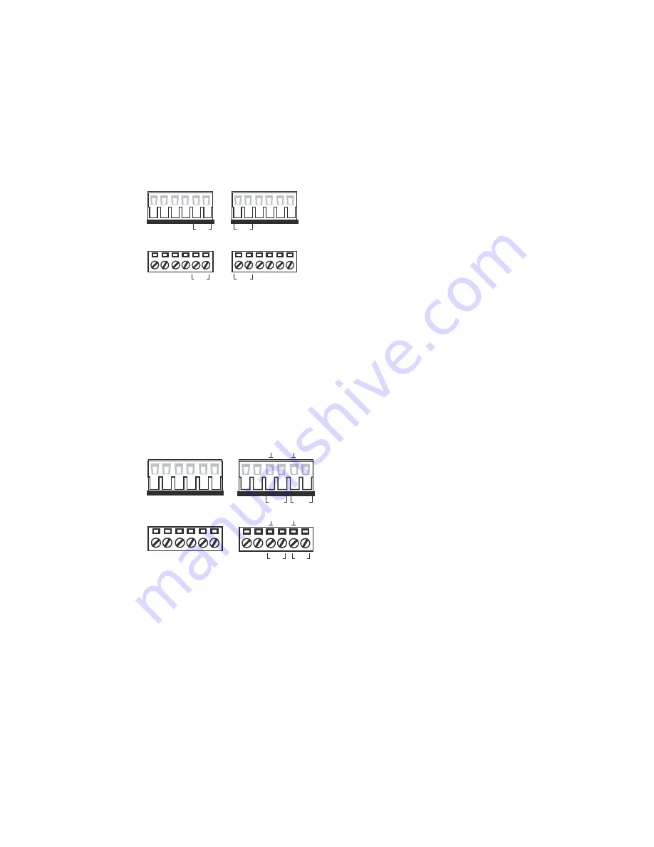
The EDS-G509 has two sets of power inputs—power input 1 and power input
2. The top two contacts and the bottom two contacts of the 6-pin terminal
block connector on the EDS-G509’s top panel are used for the two digital
inputs. The top and front views of one of the terminal block connectors are
shown here.
PWR1
PWR2
V1- V1+
PWR1
V2- V2+
PWR2
V1- V1+
V2- V2+
STEP 1
: Insert the negative/positive DC
wires into the V-/V+ terminals,
respectively.
STEP 2
: To keep the DC wires from
pulling loose, use a small flat-blade
screwdriver to tighten the wire-clamp
screws on the front of the terminal block
connector.
STEP 3
: Insert the plastic terminal block
connector prongs into the terminal block
receptor, which is located on the
EDS-G509’s top panel.
Wiring the Digital Inputs
The EDS-G509 has two sets of digital inputs, DI 1 and DI 2. Each DI consists
of two contacts of the 6-pin terminal block connector on the EDS-G509’s top
panel, which are used for the two DC inputs. The top and front views of one
of the terminal block connectors are shown here.
I
1
D 2
I
I
2
D 1
I
I
1
I
2
D 2
I
D 1
I
STEP 1
: Insert the negative
(ground)/positive DI wires into the
┴
/I1
terminals, respectively.
STEP 2
: To keep the DI wires from
pulling loose, use a small flat-blade
screwdriver to tighten the wire-clamp
screws on the front of the terminal block
connector.
STEP 3
: Insert the plastic terminal block
connector prongs into the terminal block
receptor, which is located on the
EDS-G509’s top panel.
Communication Connections
Each EDS-G509 switch has 3 types of communication port:
y
1 RJ45 console port (RS-232 interface)
y
4 10/100/1000BaseTX Ethernet ports
y
5 combination 10/100/1000T(X)/1000BaseSFP ports
RS-232 Connection
The EDS-G509 has one RS-232 (10-pin RJ45) console port, located on the
top panel. Use either an RJ45-to-DB9 (see the cable following wiring
diagrams) to connect the EDS-G509’s console port to your PC’s COM port.
You may then use a console terminal software, such as Moxa PComm


