background image


7

RELAY1 RELAY2

PWR1

PWR2

V2+

V2-

V1+

V1-

D

I

1

I

1

I

2

D

I

2

Top View

Front View

FAULT

: The two sets of relay 

contacts of the 6-pin terminal block 
connector are used to detect 
user-configured events. The two 
wires attached to the Fault contacts 
form an open circuit when a 
user-configured event is triggered. 
If a user-configured event does not 
occur, the Fault circuit will be 
closed. 

Wiring the Redundant Power Inputs 

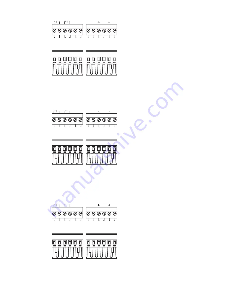
The EDS-728/828 has two sets of power input—power input 1 and power input 
2. The top two contacts and the bottom two contacts of the 6-pin terminal block 
connector on EDS’s top panel are used for EDS’s two digital inputs. 


RELAY1 RELAY2

PWR1

PWR2

V2+

V2-

V1+

V1-

D

I

1

I

1

I

2

D

I

2

Top View

Front View

STEP 1

: Insert the 

negative/positive DC wires into the 
V-/V+ terminals. 

STEP 2

: To keep the DC wires 

from pulling loose, use a small 
flat-blade screwdriver to tighten 
the wire-clamp screws on the front 
of the terminal block connector. 

STEP 3

: Insert the plastic terminal 

block connector prongs into the 
terminal block receptor, which is 
located on the EDS-728/828’s top 
panel. 

Wiring the Digital Inputs 

The EDS-728/828 has two sets of digital input—DI 1 and DI 2.


Each DI 

comprises two contacts of the 6-pin terminal block connector on EDS’s top 
panel. The terminal block is also used for EDS’s two DC inputs. Top and front 
views of one of the terminal block connectors are shown here. 


RELAY1 RELAY2

PWR1

PWR2

V2+

V2-

V1+

V1-

D

I

1

I

1

I

2

D

I

2

Top View

Front View

STEP 1

: Insert the negative 

(ground)/ positive DI wires into the 

/I1 terminals. 


STEP 2

: To keep the DI wires 

from pulling loose, use a small 
flat-blade screwdriver to tighten 
the wire-clamp screws on the front 
of the terminal block connector. 
 

STEP 3

: Insert the plastic terminal 

block connector prongs into the 
terminal block receptor, which is 
located on the EDS-728/828’s top 
panel. 

Содержание EtherDevice EDS-728 Series

Страница 1: ...S 728 828 Hardware Installation Guide First Edition January 2008 Moxa Inc Tel 886 2 8919 1230 Fax 886 2 8919 1231 www moxa com Moxa Technical support Worldwide support moxa com The Americas support usa moxa com P N 1802008280010 ...

Страница 2: ...ASTER PWR2 LNK ACT SPEED IM 4MSC TX RX 3 4 TX RX 1 2 PWR P3 P1 P4 P2 IM 4MST TX RX 3 4 TX RX 1 2 PWR P3 P1 P4 P2 3 4 IM 4TX 1 2 PWR P3 P1 P4 P2 RS 232 Console T RING 1M 2 GTX 1 1 2 2 P1 P1 P2 P2 1M 2 GSFP 1 2 5 6 8 7 9 10 11 3 4 12 RELAY1 PWR1 PWR2 V1 V2 INPUT 24VDC DI1 I1 I2 V2 V2 V1 V1 DI2 RELAY2 ...

Страница 3: ...nputs 2 DIs and 2 DOs 6 Sticker showing pin contacts 7 Serial console port 8 Screw to attach Fast Ethernet Interface Module 9 Gigabit Ethernet Module LEDs 10 Two cartridge receptors for Gigabit Ethernet Interface Modules 11 Fast Ethernet Interface Modules 12 Sockets for Fast Ethernet Interface Modules 13 DIN Rail braces 14 Ribs for radiating heat 15 Screw holes for wall mounting kit 16 Grounding s...

Страница 4: ...47 Front View EtherDevice Switch 80 6 201 2 362 40 401 00 Rear View 128 00 142 47 140 00 Side View Gigabit Ethernet Interface Modules Front View Side View 101 1 65 9 24 Fast Ethernet Interface Modules 40 127 8 127 8 100 Side View Front View EDS 728 828 ...

Страница 5: ...ttom of the top array of heat radiating ribs Press the EDS until the brace snaps into place To Release Use a flat blade screw driver as a lever to force the braces downwards and then pull the EDS 728 828 out away from the DIN Rail Wall Mounting optional For some applications you will find it convenient to mount the EDS 728 828 on the wall as illustrated below STEP 1 Remove the aluminum DIN Rail at...

Страница 6: ...serting the screw into one of the keyhole shaped apertures of the Wall Mounting Plates Do not screw the screws in all the way leave about 2 mm to allow room for sliding the wall mount panel between the wall and the screws STEP 3 Once the screws are fixed in the wall insert the four screw heads through the large parts of the keyhole shaped apertures and then slide Moxa EDS downwards as indicated Ti...

Страница 7: ...ould be kept separate The rule of thumb is that wiring that shares similar electrical characteristics can be bundled together y Keep input wiring and output wiring separated y It is strongly advised that you label wiring to all devices in the system when necessary Grounding Moxa EtherDevice Switch Grounding and wire routing help limit the effects of noise due to electromagnetic interference EMI Ru...

Страница 8: ... loose use a small flat blade screwdriver to tighten the wire clamp screws on the front of the terminal block connector STEP 3 Insert the plastic terminal block connector prongs into the terminal block receptor which is located on the EDS 728 828 s top panel Wiring the Digital Inputs The EDS 728 828 has two sets of digital input DI 1 and DI 2 Each DI comprises two contacts of the 6 pin terminal bl...

Страница 9: ...Pinout diagram below to see how RJ45 pins are numbered RS 232 Connection The EDS 728 828 has one RS 232 10 pin RJ45 console port located on the front panel Use either an RJ45 to DB9 or RJ45 to DB25 cable to connect the Moxa EDS 728 828 s console port to your PC s COM port You may then use a console terminal program to access the Moxa EDS 728 828 s console configuration utility 10 pin RJ45 Console ...

Страница 10: ...ides of the same line with the same letter A to A and B to B or A1 to A2 and B1 to B2 ATTENTION This is a Class 1 Laser LED product To avoid causing serious damage to your eyes do not stare directly into the Laser Beam LED Indicators LED Color State Description System LEDs On System has passed self diagnosis test on boot up and is ready to run GREEN Blinking System is undergoing the self diagnosis...

Страница 11: ... Mode LEDs On The corresponding module port s link is active Blinking The corresponding module port s data is being transmitted LNK ACT GREEN Off The corresponding module port s link is inactive On The corresponding module port s data is being transmitted at full duplex FDX HDX GREEN Off The corresponding module port s data is not being transmitted On The corresponding module s port is the ring po...

Страница 12: ...cols IGMP Snooping GMRP GVRP SNMP V1 V2C V3 DHCP Server Client BOOTP TFTP SNTP SMTP RARP RMON and RIP V1 V2 EDS 828 only MIB MIB II Ethernet Like MIB P BRIDGE MIB Q BRIDGE MIB Bridge MIB RSTP MIB RMON MIB Groups 1 2 3 9 Flow Control IEEE802 3x flow control back pressure Interface Fast Ethernet 6 slots for any combination of 4 port Interface Modules with 10 100BaseT X or 100BaseFX Gigabit Ethernet ...

Страница 13: ... Overload Current Protection Present Reverse Polarity Protection Present Mechanical Casing IP30 protection Dimensions 362 x 146 x 128 mm W x H x D Weight 1850g Installation DIN Rail Wall Mounting optional kit Gigabit Ethernet Interface Module IM 2G Series IM 2GTX Interface Module with 2 10 100 1000BaseT X ports RJ45 connectors IM 2GSFP Interface Module with 2 1000BaseSX LX LHX ZX SFP sockets for S...

Страница 14: ...x 3 dBm 3 dBm 2 dBm 2 dBm 2 dBm 2 dBm Min Tx 9 dBm 9 dBm 8 dBm 8 dBm 3 dBm 3 dBm Rx Sensitivity 21 dBm 21 dBm 23 dBm 23 dBm 23 dBm 23 dBm Link Budget 12 dB 12 dB 15 dB 15 dB 20 dB 20 dB Typical Distance 10 km 10 km 20 km 20 km 40 km 40 km Saturation 1 dBm 1 dBm 1 dBm 1 dBm 1 dBm 1 dBm a 50 125 μm 400 MHz km cable b 62 5 125 μm 200 MHz km cable c 50 125 μm 800 MHz km cable d 62 5 125 μm 500 MHz km ...

Страница 15: ... P3 P1 P4 P2 IM 1LSC 3TX 4 1 2 3 TX RX PWR P3 P1 P4 P2 IM 4TX IM 4MSC IM 4SSC IM 4MST IM 2MSC 2TX IM 2SSC 2TX IM 2MST 2TX IM 1LSC 3TX Interface LED Indicators PWR P1 P2 P3 P4 port status RJ45 Ports 10 100 1000BaseT X auto negotiation speed F H duplex mode and auto MDI MDI X connection Distance 100 m Fiber Ports 100BaseFX ports SC ST connector Optical Fiber Multi mode Single mode Single mode 80 km ...

Страница 16: ... EMS EN61000 4 2 ESD Level 3 EN61000 4 3 RS Level 3 EN61000 4 4 EFT Level 4 EN61000 4 5 Surge DC Input level 4 Comm Line level 3 EN61000 4 6 CS Level 3 EN61000 4 8 EN61000 4 11 EN61000 4 12 Shock IEC60068 2 27 Freefall IEC60068 2 32 Vibration IEC60068 2 6 WARRANTY 5 years Moxa Internet Services Customer satisfaction is our number one concern and to ensure that customers receive the full benefit of...

Отзывы: