


1
2
Pa
g
.
1
0
10
- M
a
n
u
a
l c
o
d
e:
1
1
9
R
7
1
7
9
G
B
11
9
R
7
1
7
9
G
B
ve
r.
3
.0
3.
0
0
7
/2
0
0
9 - T
h
e d
a
ta a
n
d i
n
fo
rm
ati
o
n i
n
th
is
m
a
n
u
a
l a
re s
u
b
je
ct t
o
c
h
a
n
g
e
at a
n
y ti
m
e
.
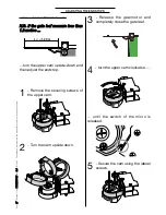
SECURING THE GEARMOTOR
1
- Remove the cover, insert
the gearmotor into the base
bracket so that it corresponds to
the 4 holes and secure it using the
supplied screws and nuts.
Warning: a sticker tag on the microswitch
shows whether that gearmotor should be
mounted to the right (DX) or to the left
(SX).
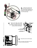
2
- Insert and secure the
straight arm into the
gearmotor shaft using plug,
screw and relative bushing.
Lubricate the bushing, insert
it into the straight arm and join
it to the curved arm using the
supplied screw, the washers
and nut.
3
- R e l e a s e t h e
gearmotor by opening
t h e h a t c h ( u s i n g t h e
apposite key); to lock it,
close the hatch.