background image

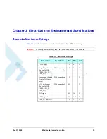
Chapter 3:  Electrical and Environmental Specifications

 May 31, 2008

Module Hardware Description

43

UART1:

21

TXD_N

UART1 TXD

O

L

15K PU

V

IH

V

IL

V

OL

V

OH

I

OUT

 < 8 mA

2

-0.3

2.575

0

3.15

0.8

0.4

V

11

RXD_N

UART1 RXD

I

L

9

RTS_N

UART1 RTS

O

L

15

CTS_N

UART1 CTS

I

L

19

DTR_N

UART1 DTR

O

L

13

DSR_N

UART1 DSR

I

L

17

DCD_N

UART1 DCD

I

L

23

RI_N

UART1 RI

I

L

UART2:

29

RXD2

UART2 RXD

I

L

15K PU

V

IH

V

IL

V

OL

V

OH

I

OUT

 < 8 mA

2

-0.3

2.75

0

3.15

0.8

0.4

V

31

TXD2

UART2 TXD

O

L

33

RTS2

UART2 RTS

O

L

35

CTS2

UART2 CTS

I

L

USB:

10

USB_VBUS

USB bus 
power

O

H

12

USB_DP

USB bus 
serial data

I/O

H

14

USB_DN

USB bus 
serial data

I/O

L

SIM Card:

50

SIM_PD_N

SIM presence 
detect

O

Refer to G24 
Hardware 
Description-

6889192V27

Stacked 
Configuration

48

SIM_VCC

SIM supply

I

44

SIM_RST_
N

SIM reset

I

52

SIM_DIO

SIM serial 
data

I/O

46

SIM_CLK

SIM clock

I

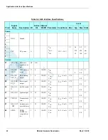
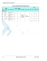
Table 3-4: G24 Interface Specifications (Cont.)

Pin #

Signal 

Name

Description I/O

Active 

H/L

Internal 

PU/PD Parameter Conditions

Level

Min

Typ

Max Units

Содержание W24

Страница 1: ...Technical Information Motorola W24 Developer s Guide Module Hardware Description MAY 31 2008 6802984C95 A ...

Страница 2: ...rola as arises by operation of law in the sale of a product Computer Software Copyrights The Motorola and 3rd Party supplied Software SW products described in this instruction manual may include copyrighted Motorola and other 3rd Party supplied computer programs stored in semiconductor memories or other media Laws in the United States and other countries preserve for Motorola and other 3rd Party s...

Страница 3: ...emarks MOTOROLA and the Stylized M Logo are registered in the US Patent Trademark Office All other product or service names are the property of their respective owners Copyright 2008 Motorola Inc REV052604 ...

Страница 4: ......

Страница 5: ...red by the Warranty xvi Installed Data xvii Out of Warranty Repairs xvii Revision History xviii Chapter 1 Introduction 1 Operation Setup 1 Stand Alone Configuration 1 Stacked Configuration 1 Product Specifications 2 Regulatory Approvals 4 CFR 47 Part 15 19 specifies Label Requirements 4 CFR 47 Part 15 21 Information to user 4 CFR 47 Part 15 247 4 CRF 47 Part 15 247 15 205 15 209 4 CFR 47 Part 15 1...

Страница 6: ...ce 23 USB Host Interface Stacked configuration only 23 SIM Interface 24 Audio Interface 25 A D Converter Interface 26 Unused Reserved Signals 27 Controls and Indicators Interface 28 Reset 28 VREF Reference Regulator 28 Wakeup 29 Antenna Detection 29 GPRS EGPRS Detection 29 Transmission Indicator 30 Wi Fi LED Indicator 30 Mode Select 30 General Purpose I O 31 Antenna Interface 33 Chapter 3 Electric...

Страница 7: ... of Contents May 31 2008 Module Hardware Description iii Required Query Information 53 Service 55 Who to Contact 55 Required Query Information 55 Testing a Standalone Unit 56 Acronyms and Abbreviations Index ...

Страница 8: ...Table of Contents iv Module Hardware Description May 31 2008 ...

Страница 9: ...5 2 6 IGN Power Off Timing 15 2 7 WKUPI_N Signal Operation 18 2 8 WKUPO_N Signal Operation 19 2 9 Serial Interface Data 20 2 10 Serial Interfaces Block Diagram 21 2 11 UART1 Interface Signals 21 4 1 W24 Mechanical Characteristics 47 4 2 W24 Stand Alone Model 48 4 3 MMCX Connector Dimensions 49 4 4 Optional MMCX Cable Assembly 50 4 5 W24 Mounting Area 51 4 6 W24 G24 Stacked Mounting 52 4 7 W24 G24 ...

Страница 10: ...alog Audio Interface Signals 25 2 9 Digital Audio Interface Signals 25 2 10 ADC Interface Signals 26 2 11 Internal Interface Signals 27 2 12 Controls and Indicators 28 2 13 VREF Specifications 29 2 14 GPIO Interface Signals 31 2 15 Antenna Interface Specifications 33 3 1 Maximum Ratings 35 3 2 Environmental Ratings 36 3 3 Host Interface Specifications 37 3 4 G24 Interface Specifications 42 4 1 W24...

Страница 11: ...d for all members of the integration team who are responsible for integrating the W24 into the host application including representatives from hardware software and RF engineering disciplines Manual Organization This manual contains the following chapters Chapter 1 introduces the W24 unit and provides important safety instructions Chapter 2 provides a detailed hardware description of the blocks an...

Страница 12: ...anufacture and intended use of the product Motorola assumes no liability for customer failure to comply with these precautions The W24 must be operated at the voltages described in the technical documentation The W24 must not be mechanically or electrically changed Use of connectors should follow the guidance of the technical documentation The W24 is designed to meet the spectrum requirements of E...

Страница 13: ...eception which can be determined by turning the equipment off and on the user is encouraged to try to correct the interference by one or more of the following measures Reorient or relocate the receiving antenna Increase the separation between the equipment and the receiver Connect the equipment to an outlet on a circuit different from that to which the receiver is connected Consult the dealer or a...

Страница 14: ... total system output must not exceed 1 0W peak output power 15 247 b Or and for meeting the EN 300 328 standard Maximum EIRP spectral density 10 dBm MHz The combined cable loss and antenna gain must not exceed 3 dBi Section 15 203 Antenna Requirement An intentional radiator shall be designed to ensure that no antenna other than that furnished by the responsible party shall be used with the device ...

Страница 15: ...phs are used in this guide to point out information that must be read This information may be set off from the surrounding text but is always preceded by a bold title in capital letters Note Note Presents additional helpful noncritical information that you can use Warning Warning Presents information to warn you of a potentially hazardous situation in which there is a possibility of personal injur...

Страница 16: ...n an explosive atmosphere Do not operate the equipment in the presence of flammable gases or fumes Operation of any electrical equipment in such an environment constitutes a definite safety hazard Do not service or adjust alone Do not attempt internal service or adjustment unless another person capable of rendering first aid is present Keep away from live circuits Operating personnel must not remo...

Страница 17: ...quipment in EU countries Disposal of Motorola equipment in EU countries Please do not dispose of Motorola equipment in landfill sites In the EU Motorola in conjunction with a recycling partner will ensure that equipment is collected and recycled according to the requirements of EU environmental law Please contact the Customer Network Resolution Center CNRC for assistance The 24 hour telephone numb...

Страница 18: ... Product at issue in the dispute except direct damages resulting from patent and or copyright infringement which shall be governed by the INDEMNITY Section of this Agreement The preceding states MOTOROLA s entire liability for MOTOROLA s breach or failure to perform under any provision of this Agreement Warranty Notification Motorola guarantees to you the original purchaser the OEM module and acce...

Страница 19: ...on to Motorola s Authorized Repair or Service Center in the original configuration and packaging as supplied by Motorola Please avoid leaving any supplementary items like SIM cards The Product should also be accompanied by a label with your name address and telephone number name of operator and a description of the problem In order to be eligible to receive warranty service you must present your r...

Страница 20: ... due to damage misuse tampering neglect or lack of care and in case of alterations or repair carried out by unauthorized persons The following are examples of defects or damage not covered by this product warranty 1 Defects or damage resulting from use of the Product in other than its normal and customary manner 2 Defects or damage from misuse access to incompatible sources accident or neglect 3 D...

Страница 21: ...or erased as part of the repair or service process Please note if you have downloaded material onto your product these may be deleted or erased as part of the repair process or testing process Motorola shall not be responsible for such matters The repair or testing process should not affect any such material that was installed by Motorola on your Product as a standard feature Out of Warranty Repai...

Страница 22: ...vision History Manual Number 6802984C95 A Manual Title Module Hardware Description Version Information The following table lists the manual version date of version and remarks about the version Revision History Version Date Issue Remarks A May 31 2008 Initial Release ...

Страница 23: ... in device firewall Operation Setup The W24 supports two operating setup configurations Stand Alone configuration Stacked assembly configuration with G24 Stand Alone Configuration Stand Alone configuration consists of a W24 as a stand alone Wi Fi module that is controlled by the host In this configuration the W24 70 pin host connector bottom connector is used for interfacing with the W24 Figure 1 ...

Страница 24: ...ety on page viii and Antenna and Transmission Safety Precautions on page ix in Preface Note Motorola reserves the right to change the specifications without prior notice G24 W24 Host PCB Table 1 1 Product Specifications Product Features Adds Wi Fi capability to G24 platforms WLAN 802 11 b g Operates in the 2 4GHz ISM band Ad Hoc WLAN Support Local WEB server Physical Characteristics Size 45 2 x 24...

Страница 25: ...es up to 3Mbps Modem UART Interface BR from 2400 bps to 230 4 kbps Extended bit rates up to 3Mbps Data Features Data Throughput Via UART 400 kbps upload 1 Mbps download security disabled 100 kbps upload 300 kbps download security enabled Via USB 800 kbps upload download security disabled 100 kbps upload 300 kbps download security enabled Control Status Indicators Wakeup Antenna Detect Reset Ready ...

Страница 26: ...ed operation CFR 47 Part 15 21 Information to user The user s manual or instruction manual for an intentional or unintentional radiator shall caution the user that changes or modifications not expressly approved by the party responsible for compliance could void the user s authority to operate the equipment In cases where the manual is provided only in a form other than paper such as on a computer...

Страница 27: ...s Reorient or relocate the receiving antenna Increase the separation between the equipment and receiver Connect the equipment into an outlet on a circuit different from that to which the receiver is connected Consult with your local dealer or with an experienced radio TV technician for help European Union Directives Conformance Statement The above gives an example of a typical Product Approval Num...

Страница 28: ...Regulatory Approvals 6 Module Hardware Description May 31 2008 ...

Страница 29: ...ting the W24 module Architecture Overview Figure 2 1 below illustrates the primary functional components of the W24 Figure 2 1 W24 Block Diagram The W24 consists of the following blocks Digital Block Micro controller Unit MCU for system and application code execution 1MByte Flash Serial communications interfaces USB Device interface USB Host interface available on cellular connector only ...

Страница 30: ...h G24 General purpose IO signals 12MHz crystal Power Management Block Power up down control circuit Power Management IC PMIC 2 LDO regulators RF Block Wireless LAN Module which includes Power Amplifier RF Transceiver RF switch Balun MAC Processor MAC EEPROM 26 MHz crystal RF Antenna connector ...

Страница 31: ...is running at 32kHz and monitoring IGN and ON_N signals Any sig nals connected to the interface connector must be set low or tri stated Sleep RESET_N signal is high CTS_N signal is disabled The W24 is in low power mode The application interfaces are disabled but W24 continues to monitor the Wi Fi network Deep Sleep RESET_N signal is high CTS_N signal is disabled The W24 enters deep sleep mode if i...

Страница 32: ... power source indirectly supplies all the digital and analog interfaces but also directly supplies the G24 RF power amplifier PA Therefore any degradation in the power supply performance due to losses noises or transients will directly affect the G24 performance The burst mode operation of the GSM transmission and reception draws instantaneous current surges from the power supply which causes temp...

Страница 33: ...ngs in various operating modes The current ratings refer to the overall W24 current consumption over the VCC supply Table 2 3 W24 Current Ratings Parameter Description Conditions Min Typ Max Unit IOFF Powered off 3 3V Vcc 4 2V 10 100 µA IOFF MODE Powered off with IGN high 3 3V VCC 4 2V IGN 0 8V 4 6 mA IDEEPSLEEP 3 3V Vcc 4 2V 4 6 mA ISLEEP Idle mode 3 3V Vcc 4 2V 9 12 mA IIDLE Idle mode 3 3V Vcc 4...

Страница 34: ...ote As the power down process in W24 is SW controlled if an unexpected reset occurs the module will power down if it is not being held by the IGN signal Therefore although both ways of powering up down are provided to user we recommend using IGN as a sole power up down control signal By using IGN as a control signal user insures that in case of an unexpected reset the unit automatically turns on I...

Страница 35: ...ing the ON_N signal low for more than 1 5 seconds may cause the W24 to interpret the signal as a power off command and turn off immediately after turning on Figure 2 3 illustrates the power on process using the ON_N signal Figure 2 3 ON_N Power On Timing Turning the W24 On Using IGN The IGN input signal must be set low when not used To turn on W24 this signal must be asserted high The IGN signal m...

Страница 36: ... unit was powered up by ON_N signal W24 will ignore attempt to turn it off by setting the IGNITION to low Attempts to power off the module within first 8 seconds from powerup must not be done The unit will ignore such attempts Turning the W24 Off Using ON_N The ON_N signal is internally pulled up when power is applied to W24 Asserting the ON_N signal low for a minimum of 2 seconds will turn W24 of...

Страница 37: ...as powered up by the IGN signal When the IGN signal is set low W24 will turn off This will initiate a normal power off process which includes G24 power down stacked configuration and disabling of all applications interfaces UART USB etc The IGN signal will not power off W24 before 30 seconds have elapsed since W24 was powered on This delay mechanism is implemented to protect W24 from unexpected tr...

Страница 38: ...utomatically without notice This form of power down is not recommended for regular use since the unexpected power loss may result in loss of data Turning the W24 Off Using AT iMRST The AT iMRST command initiates a W24 system reset operation which powers off the W24 This command emulates the ON_N signal operation for W24 power off Note In Stacked configuration AT iMRST powers down W24 only It does ...

Страница 39: ... on the serial interface or incoming from the Wi Fi network and no internal system task is running W24 will enter Sleep mode When in Sleep mode the W24 disables all its serial interfaces USB and UARTs and the VBUS output signal of the cellular connector stacked configuration The W24 continues to respond to both external and internal interrupts The following conditions must be met for the W24 to en...

Страница 40: ...ode and switching to Idle mode W24 requires a minimal delay time to reactivate and stabilize its internal circuits before it can respond to application data This delay is typically 5 milliseconds The delay guarantees that data on the serial interface is not lost or misinterpreted Temporary Termination of Low Power Mode Temporary termination of low power mode occurs when W24 switches from Sleep mod...

Страница 41: ...sserting WKUPO_N after de asserting it In other words W24 will not assert the WKUPO_N signal if the time that had passed from the previous de assertion of this signal is not at least the duration specified by the S100 parameter This time interval is required to avoid frequent unnecessary wakeup events and consequent S102 delays The S100 parameter is relevant only if S102 0 which enables the WKUPO_...

Страница 42: ...SE 0 commands is set again This command can be sent only when the serial interface is active In case the serial interface is disabled it must first be activated before sending this command To reactivate the serial interface a temporary termination of the low power mode is required as described in Temporary Termination of Low Power Mode on page 18 Following the temporary low power mode termination ...

Страница 43: ...bus The primary UART is used for all the communications with W24 AT i commands interface Wi Fi data and G24 AT command Interface stacked configuration programming and software upgrades The UART signals are active low CMOS level signals For standard RS232 communications with a PC an external transceiver is required W24 is defined as a DCE device and the user application is defined as the DTE device...

Страница 44: ...ed to the G24 interface connector by different HW wiring and the G24 will execute them Important The W24 UART will not send data over the serial interface in case the DTR_N and or RTS_N input signals are disabled set high Therefore regardless of the handshake method it is still required to enable these signals for proper operation by asserting them low Note Add a pull up resistors 22 100K on all U...

Страница 45: ...24 USB Host electrical interface and protocol conform to the USB 2 0 full speed specifications USB may be only used for standard communications between W24 and G24 stacked configuration only as done through the UART interface Setting USB Host communication is enabled by the AT iHIF 5 command Important W24 relies on the host to provide the USB_VBUS voltage for both USB device and USB host interface...

Страница 46: ...ee Table 2 7 The above signals are routed from 70 pin host connector to G24 70 pin connector via W24 They are not internally connected to W24 circuits If the W24 will be used as stand alone only the above pins should be left open For more details on implementing a SIM interface for use with G24 please refer to the Motorola G24 Developer s Guide Module Hardware Description PN 6889192V27 Table 2 7 S...

Страница 47: ...only the above pins should be left open For more details on implementing a Audio interface for use with G24 please refer to the Motorola G24 Developer s Guide Module Hardware Description PN 6889192V27 Table 2 8 Analog Audio Interface Signals Pin Pin Name Description 55 HDST_INT_N Headset detect interrupt 57 HDST_MIC Headset microphone input 59 AGND Audio ground 61 MIC Microphone input 63 ALRT_N Al...

Страница 48: ...outed from 70 pin host connector to G24 70 pin connector via W24 They are not internally connected to W24 circuits If the W24 will be used as stand alone only the above pins should be left open For more details on implementing a ADC interface for use with G24 please refer to the Motorola G24 Developer s Guide Module Hardware Description PN 6889192V27 Table 2 10 ADC Interface Signals Pin Pin Name D...

Страница 49: ...the future The signals are directly routed from 70 pin host connector to the 70 pin cellular connector The above pins should be left open Here is the summary interface consists of the following pins see Table 2 11 Table 2 11 Internal Interface Signals Pin Pin Name Description 54 LCD_CS N C 56 LCD_SD N C 58 LCD_CLK N C 70 SPI_CS N C 62 SPI_INT_N N C 64 SPI_DIN N C 68 SPI_DOUT N C 66 SPI_CLK N C ...

Страница 50: ...sabled tri state or set low when RESET_N is low VREF Reference Regulator The W24 incorporates a regulated voltage output VREF The regulator provides a 2 8V output for use by the customer application This regulator can source up to 100 mA of current to power any external digital circuits VREF voltage is present whenever the W24 is powered up regardless of it s mode of operation Table 2 12 Controls ...

Страница 51: ...nna in case that a cellular module like G24 is stacked on the W24 In case of stacked configuration W24 G24 a removal of a single or both of the modules antennas will cause the antenna detect indicator to be set Low The antenna detection state is reported to the application through the ANT_DET output signal and may also be queried by the AT iRP19 command The detection circuit senses DC resistance t...

Страница 52: ...4 circuits If the W24 will be used as stand alone only the signal pin should be left open For more details on implementing a GPRS EGPRS signal for use with G24 please refer to the Motorola G24 Developer s Guide Module Hardware Description PN 6889192V27 Wi Fi LED Indicator Wi Fi LED Indicator is an output which indicates the Wi Fi activity WIFI_LED_LCD_RS signal is mapped on the pin 60 of the 70 pi...

Страница 53: ...in Name Description 28 GPIO1 General purpose I O 30 GPIO2 General purpose I O 32 GPIO3 General purpose I O 34 GPIO4 BT_PRIORITY General purpose I O Bluetooth coexistence indication 36 GPIO5 BT_FREQ General purpose I O Bluetooth coexistence indication 38 GPIO6 BT_STATE General purpose I O Bluetooth coexistence indication 40 GPIO7 WL_ACTIVE General purpose I O Bluetooth coexistence indication 42 GPI...

Страница 54: ... transmitting high priority data the Bluetooth device shall send a 20 s pulse on this line right after BT_PRIORITY line has been asserted After this pulse BT_STATE will go LOW to indi cate RX Priority Bluetooth transmission or HIGH to indicate TX Priority BT transmission GPIO7 WL_ACTIVE O In 2 Wires coexistence When High WLAN is transmitting or receiving packets In 3 Wires coexistence When Low Blu...

Страница 55: ...performance of the W24 signal quality current consumption etc The following guidelines should be followed Make sure that the antenna or antenna assembly matches the Antenna Interface Specifications Use low loss RF cable and connectors keeping cable runs to a minimum In order to prevent mutual interference between the GSM and the WLAN antennas in stacked configuration a minimum distance that provid...

Страница 56: ...Antenna Interface 34 Module Hardware Description May 31 2008 ...

Страница 57: ...g the values may result in permanent damage to the module Table 3 1 Maximum Ratings Parameter Conditions Min Max Unit VCC Supply 0 3 4 5 V Digital Input Signals Except for IGN VBUS USB_DP USB_DN W24 powered on 0 3 3 6 V Analog Input Signals Audio A D inter faces W24 powered on 0 3 V All Input Signals Except for IGN VBUS USB_DP USB_DN W24 powered off 0 3 V IGN signal 0 3 16 V VBUS signal 0 3 5 25 V...

Страница 58: ...re not used by the customer application must be left unconnected W24 incorporates the necessary internal circuitry to keep unconnected signal in their default state Do not connect any components to or apply any voltage on signals that are not used by the application Important It is recommended to place a pull down resistor in the customer application on the IGN signal A 100 kohm resistor or less i...

Страница 59: ...lator out put O VOUT IOUT 100mA 2 7 2 8 2 9 V 16 WKUPI_N W24 wakeup input I L 15K PU VIH VIL 2 0 0 3 0 3 15 0 8 V 26 WKUPO_ N Host wakeup output O L 15K PU VOH VOL IOUT 8 mA 2 75 0 4 V 25 RESET_N W24 Ready indication output O L 15K PU VOH VOL IOUT 8 mA 2 75 0 4 V 53 ON_N On Off switch I L 100K PU VOH VOL 2 0 4 V 51 IGN Ignition input I H 80K PD VIH VIL V 39 TXEN_N Transmit indi cator O L 15K PU VO...

Страница 60: ...mA 2 0 3 2 75 0 0 3 15 0 8 0 4 V 31 TXD2 UART2 TXD I L 15K PU 33 RTS2 UART2 RTS I L 15K PU 35 CTS2 UART2 CTS O L 15K PU USB 10 USB_VBUS USB bus power I H 5 0 5 25 V 12 USB_DP USB bus serial data I O H V 14 USB_DN USB bus serial data I O L V SIM Card 50 SIM_PD_N SIM presence detect I Refer toG24 Hardware Description 6889192V27 Stacked Configuration 48 SIM_VCC SIM supply O 44 SIM_RST_ N SIM reset O ...

Страница 61: ...dio receive I Refer toG24 Hardware Description 6889192V27 Stacked Configuration 20 PCM_ DOUT Digital audio transmit O 22 PCM_CLK Digital audio clock O 24 PCM_FS Digital audio frame sync O Table 3 3 Host Interface Specifications Cont Pin Signal Name Description I O Active H L Internal PU PD Parameter Conditions Level Min Typ Max Units ...

Страница 62: ...ur pose I O I O 42 GPIO8 General pur pose I O I O Audio 67 SPKR_N Speaker inverted O Refer toG24 Hardware Description 6889192V27 Stacked Configuration 69 SPKR_P Speaker O 63 ALRT_N Alert speaker inverted O 65 ALRT_P Alert speaker O 61 MIC Microphone input I 59 AGND Audio ground 57 HDST_ MIC Headset microphone input I 55 HDST_ INT_N Headset detect inter rupt I Table 3 3 Host Interface Specification...

Страница 63: ...EL_UI D Mode Select VIH VIL 2 0 03 3 6 0 8 V Display 54 CLI_CS Do Not Use 60 WIFI_LE D_LCD_R S Wi Fi Activ ity Indicator O VOL VOH 2 75 3 15 0 4 V 56 LCD_ DATA Do Not Use 58 LCD_CLK Do Not Use Data Logger 70 SPI_CS Do Not Use 62 SPI_IRQ_ N Do Not Use 64 SPI_DIN Do Not Use 68 SPI_ DOUT Do Not Use 66 SPI_CLK Do Not Use Table 3 3 Host Interface Specifications Cont Pin Signal Name Description I O Acti...

Страница 64: ...t put NC N A 16 G24_WK UPI_N W24 wakeup input O L 15K PU VIH VIL 2 0 3 15 0 8 V 26 G24_WK UPO_N Host wakeup output I L 15K PU VOH VOL IOUT 8 mA 2 75 0 4 V 25 G24_RES ET_N Reset signal output I L 15K PU VOH VOL IOUT 8 mA 2 75 0 4 V 53 G24_ON_ N On Off switch O L 15K PU VOH VOL 2 75 0 4 V 51 G24_IGN Ignition input O H 15K PU VIH VIL 2 0 4 V 39 TXEN_N Transmit indi cator I L 15K PU VOH VOL IOUT 8 mA ...

Страница 65: ...IH VIL VOL VOH IOUT 8 mA 2 0 3 2 75 0 3 15 0 8 0 4 V 31 TXD2 UART2 TXD O L 33 RTS2 UART2 RTS O L 35 CTS2 UART2 CTS I L USB 10 USB_VBUS USB bus power O H 12 USB_DP USB bus serial data I O H 14 USB_DN USB bus serial data I O L SIM Card 50 SIM_PD_N SIM presence detect O Refer toG24 Hardware Description 6889192V27 Stacked Configuration 48 SIM_VCC SIM supply I 44 SIM_RST_ N SIM reset I 52 SIM_DIO SIM s...

Страница 66: ...ive O Refer toG24 Hardware Description 6889192V27 Stacked Configuration 20 PCM_ DOUT Digital audio transmit I 22 PCM_CLK Digital audio clock I 24 PCM_FS Digital audio frame sync I Table 3 4 G24 Interface Specifications Cont Pin Signal Name Description I O Active H L Internal PU PD Parameter Conditions Level Min Typ Max Units ...

Страница 67: ...General pur pose I O I O 42 GPIO8 General pur pose I O I O Audio 67 SPKR_N Speaker inverted I Refer toG24 Hardware Description 6889192V27 Stacked Configuration 69 SPKR_P Speaker I 63 ALRT_N Alert speaker inverted I 65 ALRT_P Alert speaker I 61 MIC Microphone input O 59 AGND Audio ground 57 HDST_ MIC Headset microphone input O 55 HDST_ INT_N Headset detect inter rupt O Table 3 4 G24 Interface Speci...

Страница 68: ... ADC3 General pur pose A D O 45 UID Do Not Use Display 54 CLI_CS Do Not Use 60 LCD_RS Do Not Use 56 LCD_ DATA Do Not Use 58 LCD_CLK Do Not Use Data Logger 70 SPI_CS Do Not Use 62 SPI_IRQ_ N Do Not Use 64 SPI_DIN Do Not Use 68 SPI_ DOUT Do Not Use 66 SPI_CLK Do Not Use Table 3 4 G24 Interface Specifications Cont Pin Signal Name Description I O Active H L Internal PU PD Parameter Conditions Level Mi...

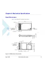
Страница 69: ...May 31 2008 Module Hardware Description 47 Chapter 4 Mechanical Specifications Board Dimensions Figure 4 1 describes the W24 mechanical characteristics Figure 4 1 W24 Mechanical Characteristics ...

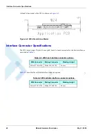
Страница 70: ... pin 0 5 mm pitch board to board connector for the host interface as described in Table 4 1 Table 4 2 describes the cellular interface connector options Table 4 1 W24 host interface connector options W24 Connector Mating Connector Stacking Height Molex 53748 0708 Molex 52991 0708 3 0 mm Table 4 2 W24 cellular interface connector options W24 Connector Mating Connector Stacking Height Molex 52991 07...

Страница 71: ...ating Connector The RF mating connector should be a standard MMCX plug connector or cable assembly which corresponds to the W24 MMCX connector specifications Any standard MMCX connector or application from different manufacturers may be mated with W24 Table 4 3 RF Connector Specifications Parameter Specifications Impedance 50 Ω Rated Voltage 335 VRMS Contact Resistance 5 mΩ center contact 2 5 mΩ o...

Страница 72: ...tor Specifications 50 Module Hardware Description May 31 2008 Such a cable assembly example is the Huber Suhner PN 11_MMCX 50 1 2 111_OH which is illustrated in Figure 4 4 Figure 4 4 Optional MMCX Cable Assembly ...

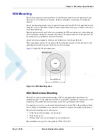
Страница 73: ...nts which are not shielded are located near the holes These components must not be in contact with the mounting elements or with other parts of the application board and care must be taken to avoid any damage Figure 4 5 depict the W24 mounting area Figure 4 5 W24 Mounting Area W24 Stand Alone Mounting The holes are used for mechanical mounting of W24 to the application board but also for grounding...

Страница 74: ...5 Lb In W24 G24 Stacked Mounting When G24 module is stacked on W24 and mounted on the host PCB it is required to use hexagonal spacer x2 between the two PCB s see Figure 4 6 Figure 4 6 W24 G24 Stacked Mounting Recommended spacer dimensions are described in Figure 4 7 Recommended spacer tightening force 3 0 Lb In Figure 4 7 W24 G24 Stacked Mounting Spacer Dimensions ...

Страница 75: ...The support services provided by Motorola are subject to the agreement between the customer and Motorola and may be at an additional charge to the customer Motorola will inform the customer in advance of any such charge Indirect Customer Send requests to your distributor and not to Motorola help desk Required Query Information Every new call problem report directly from a Direct Customer or from a...

Страница 76: ... of all the commands and the responses beginning from startup Answers to the following questions Was the same scenario tested on the Developer Board and the PC to reproduce the problem How many units do you have and how many of them have this problem How often does the problem recur In addition to the information requested above send the following AT commands and the HyperTerminal log with the res...

Страница 77: ...r and not Motorola field service department Required Query Information To apply for analysis or replacement of modules within the warranty period the following information must be provided 1 Model 2 MSN Motorola Serial Number 3 Defect Symptom for every unit deeper details required for analysis 4 Requester full information Name company phone email Populate all the above into an excel file and email...

Страница 78: ...ly a few of the W24 s many features Using this setup you can perform several additional tests on the W24 The test requires knowledge about the operation of the M2M Developer s Kit terminal applications and AT and AT i commands Refer to relevant documentation for assistance To perform the test you need the following A W24 OEM cellular engine unit A W24 Developer s Kit A desktop or laptop computer w...

Страница 79: ...s D DCS Digital Cellular System GSM in the 1800MHz band D DOC Department of Communications Canada D DRX Discontinuos Reception D DSP Digital Signal Processor D DSR Data Set Ready D DTE Data Terminal Equipment such as terminals PCs and so on D DTMF Dual Tone MultiFrequency D DTR Data Terminal Ready D DTX Discontinuos Transmission E EFR Enhanced Full Rate E EGPRS Enhanced General Packet Radio Servic...

Страница 80: ...roval G GCF GSM Certification Forum G GPIO General Purpose Input Output G GPRS General Packet Radio Service G GSM Global System for Mobile Communications H HR Half Rate I IC Integrated Circuit L LNA Low noise Amplifier M MMCX Miniature Micro Coax M MO Mobile Originated M MT Mobile Terminated O OEM Original Equipment Manufacturer P PCB Printed Circuit Board P PCL Power Class Level P PCM Pulse Code ...

Страница 81: ...U Pull Up R R TTE Radio and Telecommunications Terminal Equipment R RMS Root Mean Square R RI Ring Indicator R RTS Request To Send S SAR Specific Absorption Rate S SIM Subscriber Identity Module S SMS Short Message Service S SPI Serial Peripheral Interface T TDMA Time Division Multiple Access T TIS Transmitter Isotropic Sensitivity T TRP Transmitter Radiated Power Abbreviation Full Name R S T ...

Страница 82: ...tion May 31 2008 U UART Universal Asynchronous Receiver Transmitter U USB Universal Serial Bus U USSD Unstructured Supplementary Services Data V VCC Voltage Common Collector V VSWR Voltage Standing Wave Ratio Abbreviation Full Name U V ...

Страница 83: ...ons 2 Precautions ix Product Specifications 3 R Regulatory Approvals 4 S Safety Precautions ix Specifications 2 Environmental 3 Physical 2 Standards x Support Center 53 T Terms 2 Testing 56 U User Operation ix W W24 Abbreviations 2 Antenna Installation x Block Diagram Description 7 Product Specifications 2 Regulatory Approvals 4 Safety Precautions ix Standards x Terms and Abbreviations 2 Testing 5...

Страница 84: ...Index W W Index 2 Module Hardware Description May 31 2008 ...

Страница 85: ......

Страница 86: ...e names are the property of their respective owners Copyright 2007 Motorola Inc Java Technology and or J2ME Java and all other Java based marks are trademarks or registered trademarks of Sun Microsystems Inc in the U S and other countries UNIX UNIX is a registered trademark of The Open Group in the United States and other countries ...

Отзывы: