


SIM Interface
24
Module Hardware Description
May 31, 2008
For more details on setting a USB interface for use with G24, please refer to the
"Motorola W24
Programmer's Guide - At+i Programmers Manual Description" PN 6802985C10
.
Note:
The maximum length of the W24 USB signals is 1m.
SIM Interface
W24 incorporates SIM interface intended to support G24 SIM interface, in stacked configuration.
The interface consists of the following pins (see
Table 2-7
):
The above signals are routed from 70-pin host connector to G24 70-pin connector via W24. They
are not internally connected to W24 circuits. If the W24 will be used as stand alone only, the
above pins should be left open.
For more details on implementing a SIM interface for use with G24, please refer to the
"Motorola
G24 Developer's Guide - Module Hardware Description" PN 6889192V27
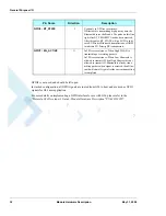
Table 2-7: SIM Interface Signals
Pin #
Pin Name
Description
44
SIM_RST_N
Active low SIM reset signal
46
SIM_CLK
SIM Clock
48
SIM_VCC
SIM Voltage Supply
50
SIM_PD_N
Active low SIM card presence
detection
52
SIM_DIO
Serial input and output data
Содержание W24
Страница 4: ......
Страница 8: ...Table of Contents iv Module Hardware Description May 31 2008 ...
Страница 28: ...Regulatory Approvals 6 Module Hardware Description May 31 2008 ...
Страница 56: ...Antenna Interface 34 Module Hardware Description May 31 2008 ...
Страница 84: ...Index W W Index 2 Module Hardware Description May 31 2008 ...
Страница 85: ......