background image

3-6

SE4400 Integration Guide

Decode Zones

SE4400-E000E

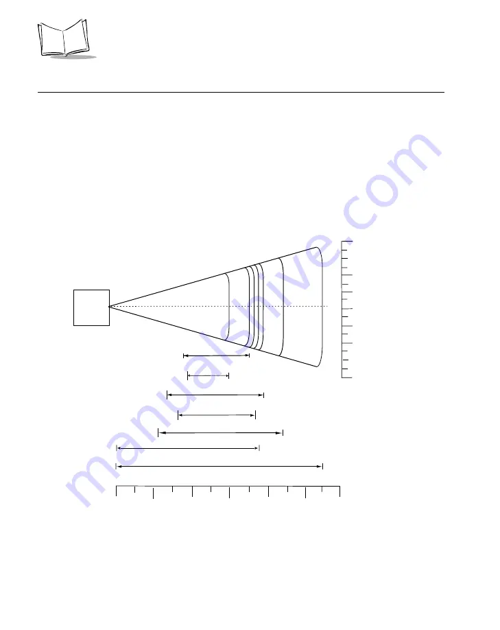
Near Focus

Figure 3-2

 shows the decode zone for the Near Focus SE4400-E000E. Typical values 

appear

Table 3-2

 lists the typical and guaranteed distances for selected bar code densities. 

The minimum element width (or “symbol density”) is the width in mils of the narrowest 
element (bar or space) in the symbol.

Figure 3-2.  SE4400-E000E Near Focus Decode Zone

In.

cm

0

20 mil

Depth of Field

11

2

4

6

8

10

0

5.1

10.2

15.2

20.3

25.4

13 mil (100% UPC)

7.5

5 mil

2.25

8.75

3.5

7.0

15 mil PDF417

0

      cm

W

i

d

t

h

o

f

F

i

e

l

d

0

1.75 4.4

3.5

8.9

8.9

*

*

* Minimum distance determined by symbol length and scan angle.

1.75

3.5

4.4

      in.

Note:  Typical performance at 73˚F (23˚C) 
           on high quality symbols in normal room light.
           Vcc = 3.3V

12

30.5

7.5 mil

2.75

7.75

6.67 mil PDF417

3.75

6.0

10 mil PDF417

3.25

7.25

SE 4400

Содержание Symbol SE4400

Страница 1: ...SE4400 Integration Guide ...

Страница 2: ......

Страница 3: ...SE4400 Integration Guide 72E 63399 04 Revision A January 2007 ...

Страница 4: ... derivative work from a licensed program or use a licensed program in a network without written permission from Motorola The user agrees to maintain Motorola s copyright notice on the licensed programs delivered hereunder and to include the same on any authorized copies it makes in whole or in part The user agrees not to decompile disassemble decode or reverse engineer any licensed program deliver...

Страница 5: ...l manual are listed below Change Date Description 72E 63399 01 6 2004 Initial release 72E 63399 02 8 2004 Updated mechanical drawing 72E 63399 03 4 2006 Update with engineering changes 72E 63399 04 1 2007 Added SE4400 E004E version decode ranges ...

Страница 6: ...iv ...

Страница 7: ...E4400 1 2 Aiming System 1 3 Aiming Error 1 3 Aiming Control 1 4 Illumination System 1 4 Illumination Control 1 4 Focus Control 1 4 Chapter 2 Installation Overview 2 1 General Information 2 1 Grounding 2 1 Electrostatic Discharge ESD 2 1 Environment 2 1 Mounting 2 2 Housing Design 2 4 Optical 2 4 Positioning the Exit Window 2 4 Avoiding Scratched Windows 2 4 Window Material 2 4 ...

Страница 8: ...Overview 4 1 SE4400 4 1 Connector Drawings 4 4 Molex Connector Specifications 4 7 Connector Insertion Withdrawal Force 4 10 Connector Retention Force min 4 10 Chapter 5 Application Notes Overview 5 1 Image Acquisition 5 1 Mode 3 5 3 Startup Procedure 5 3 Image Acquisition Procedure 5 6 Mode 1 5 9 Startup Procedure 5 9 Image Acquisition Procedure 5 11 Power Modes 5 13 Motor Control 5 16 Exposure Ga...

Страница 9: ...vii Contents Index Feedback ...

Страница 10: ...viii SE4400 Integration Guide ...

Страница 11: ...apter Descriptions The manual includes the following chapters Chapter 1 Getting Started provides an overview of the engine and the theory of operation Chapter 2 Installation explains how to install the engine including information on mounting housing design grounding ESD and environmental considerations Chapter 3 SE4400 Specifications provides technical specifications for the engine including deco...

Страница 12: ...have a problem with your equipment contact the Symbol Global Customer Interactive Center at http www symbol com customersupport Call the Global Customer Interactive Center from a phone near the equipment so that the service representative can try to talk you through your problem Have the model number and serial number of your product with you If your problem cannot be solved over the phone you may...

Страница 13: ...RH Class II IEC Class I laser light Do not stare into beam Overview The SE4400 provides digital images which can be transmitted to a decoder to decode a bar code of any format supported by the decoding software The SE4400 uses laser aiming and LED illumination and can switch between two focus positions for extended working range or for more precise focusing in high density bar code decoding or dig...

Страница 14: ...t data output grayscale for each pixel of the CCD sensor array Figure 1 1 provides a block diagram of the imager system Figure 1 1 SE4400 Block Diagram Monochrome VGA CCD DC DC Converter Driver Timing Generator Analog Gain 8 bit A D Converter Line Memory Registers Pixel Data Cam Control I2C Bi Focus Motor H Bridge Motor Drive Focus Control Laser Drive Circuitry Aiming LED FET Switch Aim Enable Ill...

Страница 15: ...accompanied by a signal processing companion multi chip module MCM which contains the charge pumps and timing generator needed to drive the CCD The MCM also contains a correlated double sampler CDS and A D converter to convert the analog voltage output by the CCD into an 8 bit digital value representing one of 256 shades of gray Aiming System A 650 nm laser and a DOE generate a laser aiming patter...

Страница 16: ...ge of ambient lighting total darkness to full sunlight Illumination Control The SE4400 can capture images with the illumination subsystem turned on or off accommodating images that are close to the wavelength of the illumination For example since red LED illumination is used it may be desirable to shut off the illumination when capturing a printed image in red ink Focus Control The SE4400 has two ...

Страница 17: ...atic Discharge ESD The SE4400 is protected from ESD events that may occur in an ESD controlled environment Use care when handling this component and apply standard ESD handling procedures such as using grounding wrist straps and handling in a properly grounded work area Environment The engine and decoder must be sufficiently enclosed to prevent dust from gathering on the laser lens optical lens il...

Страница 18: ... orientation without degradation in performance Note Mounting the SE4400 in a non upright position results in images rotated accordingly in snapshot or video mode When installing the mounting screws ensure they do not protrude past the mounting hole threads in the chassis use 2 4 mm maximum mounting screw thread engagement Recommended mounting screw torque is 1 25 0 25 in lb ...

Страница 19: ... 24o Nominal illumination envelope is 40o cone Maximum envelopes do not include integration tolerances SE4400 may be located with 1 2mm maximum long pins in 2 places marked A Do not place any magnetic material within 1 inch of the chassis without testing performance This is a reference drawing and is not intended to specify or guarantee all possible integration requirements for this engine ...

Страница 20: ...ch larger imagers However the performance of the SE4400 can be affected by an improperly designed enclosure or improper selection of window material Positioning the Exit Window Position the window so that illumination system light reflected off the inside of the window is not reflected back into the engine see Table 2 4 on page 2 9 The specified angles are minimums allow for manufacturing toleranc...

Страница 21: ...ed by cell casting Most plastic eyeglasses sold today are uncoated cell cast CR 39 This material has excellent chemical and environmental resistance and reasonably good impact resistance It also has quite good surface hardness and therefore does not have to be hard coated but may be coated for severe environments This material cannot be ultrasonically welded Chemically Tempered Float Glass Glass i...

Страница 22: ...ratch and abrasion To apply dip and air dry in an oven with filtered hot air To gauge a window s durability use ASTM standard D1044 Standard Test Method for Resistance of Transparent Plastics to Surface Abrasion the Taber Test which quantifies abrasion resistance as a percent increase in haze after a specified number of cycles and load Lower values of the increase in haze correspond to better abra...

Страница 23: ...atches and digs If using an anti reflective coating the specifications in Table 2 3 apply Table 2 3 AR Coatings Specifications Material Both tempered glass and plastic e g CR 39 or hard coated acrylic exit windows can be AR coated AR coated glass is easier and more durable because of a better adhesion property on the glass structure In addition it can be more cost effective to put an AR coating on...

Страница 24: ...2 8 SE4400 Integration Guide Optical Path and Exit Window Figure 2 2 SE4400 Optical Path and Exit Window ...

Страница 25: ... Positive Angle C 6 7 7 5 8 3 11 0 12 8 14 7 C1 mm C2 mm 4 6 2 1 5 1 2 4 5 1 3 2 6 5 4 5 7 5 5 3 8 5 6 2 Minimum Window Clear Aperture Width F1 F2 mm Positive Angle F 10 1 10 8 13 1 16 3 18 4 20 7 F1 mm F2 mm 2 4 7 7 2 7 8 1 3 8 9 3 5 7 10 6 6 7 11 7 7 8 12 9 Minimum Window Tilt Non A R Coated Negative Angle D 0 0o 0 5o 0 0o 0 5o 30o 35o 35o 35o Minimum Window Clear Aperture Height E1 E2 mm Negati...

Страница 26: ...ons are followed there is no impact on the performance of near or far distances The terminology near or far image focusing is used to depict different performance configurations Test condition was set at 10 maximum millisecond exposure time and 127 maximum gain Consider anti reflection coating if the exposure time is more than 10 msec For example for a 30 msec exposure time use a double sided AR c...

Страница 27: ...l Laser Current Peak Camera Current Illumination Current 2 85 V to 3 45 V 79 mA typical 30 mA typical 45 mA typical 320 mA duration 88 µs 36 mA 3 0 V typical 47 mA 3 3 V typical Maximum Power Supply Noise 75 mVp p at 3 3 VDC for decoding 30 mVp p at 3 3 VDC for picture taking The bar code may decode even with visible noise on the image For best image quality when taking pictures use a filter to su...

Страница 28: ...e Figure on page 3 4 Roll 360º see Figure on page 3 4 Ambient Light Immunity Sunlight 9000 ft candles 96 900 lux Scan Element Image Resolution Gray Level Field of View FOV 640 x 480 pixels VGA type CCD 256 shades of gray 32 2º horizontal 24 5º vertical Focusing Distance from Front of Engine Near Focus Far Focus 5 inches 9 inches Aiming Element Visible Laser Diode VLD VLD Power Pattern Angle Aiming...

Страница 29: ...tave ESD 500 V pin injection Laser Class The engine by itself is an unclassified component It is intended for use in CDRH Class II IEC Class 1 devices with proper housing labeling and instructions to comply with federal and or international standards Temperature Operating Storage 20º to 55º C 4º to 131º F 40º to 70º C 40º to 158ºF Humidity Operating Storage 95 RH non condensing at 60º C 85 RH non ...

Страница 30: ...ameters are not cumulative A thermal analysis is recommended if the application is subject to an extreme temperature environment Skew Pitch and Roll Measured on a 20 mil Code 39 symbol at a distance of 10 inches Tolerance is reduced at extreme ends of the working range ...

Страница 31: ...3 5 SE4400 Specifications Figure 3 1 Skew Pitch and Roll Skew Pitch Roll Note Tolerances are of the working range reduced at extreme ends 50 from normal 60 from normal 360 ...

Страница 32: ...west element bar or space in the symbol Figure 3 2 SE4400 E000E Near Focus Decode Zone In cm 0 20 mil Depth of Field 11 2 4 6 8 10 0 5 1 10 2 15 2 20 3 25 4 13 mil 100 UPC 7 5 5 mil 2 25 8 75 3 5 7 0 15 mil PDF417 0 cm W i d t h o f F i e l d 0 1 75 4 4 3 5 8 9 8 9 Minimum distance determined by symbol length and scan angle 1 75 3 5 4 4 in Note Typical performance at 73 F 23 C on high quality symb...

Страница 33: ...n 7 0 cm 7 75 in 19 7 cm 3 5 in 8 9 cm 6 5 in 16 5 cm 10 mil PDF417 3 Col 17 Rows 80 MRD 3 25 in 8 3 cm 7 25 in 18 4 cm 4 0 in 10 2 cm 6 5 in 16 5 cm 13 mil UPC A 012345678905 80 MRD 2 25 in 5 7 cm 8 75 in 22 2 cm 3 0 in 7 6 cm 7 0 in 17 8 cm 15 mil PDF417 80 MRD Note 1 7 5 in 19 1 cm Note 1 7 0 in 17 8 cm 20 mil Code 39 123 80 MRD Note 1 11 0 in 27 9 cm Note 1 9 5 in 24 1 cm Notes 1 Near distance...

Страница 34: ...narrowest element bar or space in the symbol Figure 3 3 SE4400 E000E Far Focus Decode Zone In cm 0 20 mil Depth of Field 21 5 5 10 15 20 25 0 12 7 25 4 38 1 50 8 63 5 13 mil 100 UPC 13 75 5 mil 3 16 6 5 7 5 15 mil PDF417 0 cm W i d t h o f F i e l d 0 4 10 2 8 20 3 20 3 Minimum distance determined by symbol length and scan angle 8 10 2 in Note Typical performance at 73 F 23 C on high quality symbo...

Страница 35: ...n 14 0 cm 8 5 in 21 6 cm 10 mil PDF417 3 Col 17 Rows 80 MRD 5 75 in 14 6 cm 10 25 in 26 0 cm 6 5 in 16 5 cm 9 5 in 24 1 cm 13 mil UPC A 012345678905 80 MRD 3 0 in 7 6 cm 16 0 in 40 6 cm 3 75 in 9 5 cm 13 in 33 0 cm 15 mil PDF417 80 MRD Note 1 13 75 in 34 9 cm Note 1 12 75 in 32 4 cm 20 mil Code 39 123 80 MRD Note 1 21 5 in 51 6 cm Note 1 17 0 in 43 2 cm Notes 1 Near distances are FOV limited 2 Con...

Страница 36: ...lement bar or space in the symbol Figure 3 4 SE4400 E000E Toggled Focus Decode Zone In cm 0 20 mil Depth of Field 21 5 5 10 15 20 25 0 12 7 25 4 38 1 50 8 63 5 13 mil 100 UPC 13 75 5 mil 2 25 16 3 5 7 5 15 mil PDF417 Minimum distance determined by symbol length and scan angle Note Typical performance at 73 F 23 C on high quality symbols in normal room light Vcc 3 3V 7 5 mil 2 75 10 10 mil PDF417 3...

Страница 37: ...D 2 75 in 7 0 cm 10 0 in 25 4 cm 3 5 in 8 9 cm 8 5 in 21 6 cm 10 mil PDF417 3 Col 17 Rows 80 MRD 3 25 in 8 3 cm 10 25 in 26 0 cm 4 0 in 10 2 cm 9 5 in 24 1 cm 13 mil UPC A 012345678905 80 MRD 2 25 in 5 7 cm 16 0 in 40 6 cm 3 0 in 7 6 cm 13 in 33 0 cm 15 mil PDF417 80 MRD Note 1 13 75 in 34 9 cm Note 1 12 75 in 32 4 cm 20 mil Code 39 123 80 MRD Note 1 21 5 in 51 6 cm Note 1 17 0 in 43 2 cm Notes 1 ...

Страница 38: ...n 17 5 cm Far 4 25 in 10 8 cm 7 125 in 18 1 cm 10 mil PDF417 3 Col 17 Rows 80 MRD Near 3 25 in 8 3 cm 6 375 in 16 2 cm Far 5 75 in 14 6 cm 7 25 in 18 4 cm 13 mil UPC A 012345678905 80 MRD Near 2 25 in 5 7 cm 7 375 in 18 7 cm Far 3 00 in 7 6 cm 8 375 in 21 3 cm Notes 1 Near distances are FOV limited 2 Contrast is measured as Mean Reflective Difference MRD at 670 nm 3 Working range specifications at...

Страница 39: ...pe Bar Code Content ContrastNote 2 Focus Position Typical Working Ranges Near Far Notes 1 Near distances are FOV limited 2 Contrast is measured as Mean Reflective Difference MRD at 670 nm 3 Working range specifications at temperature 23 C pitch 15 roll 0 skew 0 photographic quality humidity 45 70 RH 4 Range measurements are when VCC_ILLUM is powered off of 3 0 V see Table 4 1 on page 4 1 Powering ...

Страница 40: ...ment bar or space in the symbol Figure 3 5 SE4400 E004E Near Focus Decode Zone In cm 0 20 mil Depth of Field 7 5 1 2 3 4 5 0 2 5 10 2 7 6 10 2 12 7 13 mil 100 UPC 5 0 5 mil 2 4 5 8 2 2 4 5 15 mil PDF417 0 cm 0 3 8 3 0 7 6 7 6 Minimum distance determined by symbol length and scan angle 3 0 in Note Typical performance at 73 F 23 C on high quality symbols in normal room light Vcc 3 3V 6 15 2 7 5 mil ...

Страница 41: ...cm 7 5 mil Code 39 ABCDEF 80 MRD 2 1 in 5 33 cm 4 8 in 12 19 cm 3 0 in 7 62 cm 4 0 in 10 16 cm 10 mil PDF417 3 Col 17 Rows 80 MRD 2 2 in Note 1 5 59 cm 4 5 in 11 43 cm Note 1 3 75 in 9 53 cm 13 mil UPC A 012345678905 80 MRD 2 4 in 6 10 cm 5 8 in 14 73 cm Note 1 4 5 in 11 43 cm 15 mil PDF417 80 MRD Note 1 5 0 in 12 7 cm Note 1 4 25 in 10 80 cm 20 mil Code 39 123 80 MRD Note 1 7 5 in 19 05 cm Note 1...

Страница 42: ...ment bar or space in the symbol Figure 3 6 SE4400 E004E Far Focus Decode Zone In cm 0 20 mil Depth of Field 15 0 3 6 9 12 15 0 7 6 15 2 22 9 30 5 38 1 13 mil 100 UPC 10 3 5 mil 3 2 12 2 4 3 7 0 15 mil PDF417 0 cm W i d t h o f F i e l d 0 2 5 1 4 10 2 10 2 Minimum distance determined by symbol length and scan angle 4 5 1 in Note Typical performance at 73 F 23 C on high quality symbols in normal ro...

Страница 43: ...MRD 3 3 in 8 38 cm 9 8 in 24 89 cm 4 5 in 11 43 cm 7 75 in 19 69 cm 10 mil PDF417 3 Col 17 Rows 80 MRD 4 3 in 10 92 cm 9 0 in 22 86 cm 5 75 in 14 61 cm 7 5 in 19 05 cm 13 mil UPC A 012345678905 80 MRD 3 2 in 8 13 cm 12 2 in 30 99 cm 3 75 in 9 53 cm 8 75 in 22 23 cm 15 mil PDF417 80 MRD 3 2 in Note 1 8 13 cm 10 3 in 26 16 cm Note 1 8 25 in 20 96 cm 20 mil Code 39 123 80 MRD Note 1 15 0 in 38 1 cm N...

Страница 44: ... element bar or space in the symbol Figure 3 7 SE4400 E004E Toggled Focus Decode Zone In cm 0 20 mil Depth of Field 15 0 3 6 9 12 15 0 7 6 15 2 22 9 30 5 38 1 13 mil 100 UPC 10 3 5 mil 2 4 12 2 2 2 7 0 15 mil PDF417 0 cm W i d t h o f F i e l d 0 2 5 1 4 10 2 10 2 Minimum distance determined by symbol length and scan angle 4 5 1 in Note Typical performance at 73 F 23 C on high quality symbols in n...

Страница 45: ... mil Code 39 ABCDEF 80 MRD 2 1 in 5 33 cm 9 8 in 24 89 cm 3 0 in 7 62 cm 7 75 in 19 69 cm 10 mil PDF417 3 Col 17 Rows 80 MRD 2 2 in Note 1 5 59 cm 9 0 in 22 86 cm Note 1 7 5 in 19 05 cm 13 mil UPC A 012345678905 80 MRD 2 4 in 6 10 cm 12 2 in 30 99 cm Note 1 8 75 in 22 23 cm 15 mil PDF417 80 MRD Note 1 10 3 in 26 16 cm Note 1 8 25 in 20 96 cm 20 mil Code 39 123 80 MRD Note 1 15 0 in 38 1 cm Note 1 ...

Страница 46: ...in 10 41 cm Far 5 1 in 12 95 cm 7 5 in 19 05 cm 7 5 mil Code 39 ABCDEF 80 MRD Near 2 2 in 5 59 cm 4 8 in 12 19 cm Far 3 3 in 8 38 cm 8 7 in 22 10 cm 10 mil PDF417 3 Col 17 Rows 80 MRD Near 2 3 inNote 1 5 84 cm 4 5 in 11 43 cm Far 4 3 in 10 92 cm 9 0 in 22 86 cm Notes 1 Near distances are FOV limited 2 Contrast is measured as Mean Reflective Difference MRD at 670 nm 3 Working range specifications a...

Страница 47: ...e Distances in Darkness Continued Symbol Density Bar Code Type Bar Code Content ContrastNote 2 Focus Position Typical Working Ranges Near Far Notes 1 Near distances are FOV limited 2 Contrast is measured as Mean Reflective Difference MRD at 670 nm 3 Working range specifications at temperature 23 C pitch 15 roll 0 skew 0 photographic quality humidity 45 70 RH 4 Range measurements are when VCC_ILLUM...

Страница 48: ...3 22 SE4400 Integration Guide ...

Страница 49: ...ts the pins and signals of the 31 pin connector on the SE4400 Table 4 1 SE4400 Signal Information Pin Number SE4400 Signal Name I O Note 1 GND Pwr Ground 2 PCLK O Pixel Clock 3 GND Pwr Ground 4 HREF O Horizontal Pixel Valid Clock Sync 5 VCC_MOTOR Pwr Focus Control Motor Power 6 VCC_ILLUM Pwr Illumination Power 7 REG_RESET I O I2 C Register Reset Pin 8 VCC Pwr CCD Aiming Power 9 VCC Pwr CCD Aiming ...

Страница 50: ...B 14 PIX_D1 O Pixel Data Bit 1 15 PIX_D2 O Pixel Data Bit 2 16 PIX_D3 O Pixel Data Bit 3 17 PIX_D4 O Pixel Data Bit 4 18 PIX_D5 O Pixel Data Bit 5 19 PIX_D6 O Pixel Data Bit 6 20 PIX_D7 O Pixel Data Bit 7 21 FOCUS_CTRL1 I Focus Control Line 1 22 VREF O Vertical Frame Valid Clock Sync 23 EXHT I External Horizontal Clock 24 I2C_SDA I O I2 C BUS Data Line 25 I2C_SCL I I2 C BUS Clock Line 26 GND Pwr G...

Страница 51: ...ugh PIX_D7 are in the output state in acquisition mode and are brought low in stand by mode If CS is brought high the pixel data lines are in the output state during acquisition mode and are in a Hi Z state during stand by mode The latter option accommodates a multi camera system ...

Страница 52: ...63 Notes 1 Dimensions are in mm in 2 Material Housing LCP UL94V 0 Actuator PPS UL94V 0 Terminal phosphor bronze Sn Pb over Cu plating Stopper phosphor bronze Sn Pb over Cu plating 3 Misalignment of solder tails and fitting nails from Upper direction 0 max Lower direction 0 1 max Offset between solder tails and fitting nails 0 1 max 4 General tolerances 0 3 R ...

Страница 53: ...4 5 Electrical Interface Figure 4 2 31 Pin ZIF Connector p n 50 12100 1002 continued Dimensions are in mm unless otherwise specified ...

Страница 54: ...lymide per IPC 4203 1 3 Finish All exposed copper areas are to be white tin plated to a thickness of 25 microinches average thickness 4 Workmanship standards shall be in accordance with IPC 6011 Class 2 and IPC 6013 type 1 5 Supplied gerber data Minimum conductor width 0 10 mm Minimum spacing to be 0 08 mm except in connector area 6 Dimensions are to center of contact 7 Scalloped ends are optional...

Страница 55: ...C rms for 1 minute between adjacent terminal or ground JIS C5402 5 1 MIL STD 202 Method 301 No breakdown Mechanical Performance FPC Insertion Withdrawal Force Insert and withdraw FPC at the rate of 25 3 mm minute See Table 4 3 on page 4 10 FPC Retention Force Insert the actuator pull the FPC at the rate of 25 3 mm minute See Connector Retention Force min on page 4 10 Terminal Retention Force Apply...

Страница 56: ... Z axes JIS C0041 MIL STD 202 Method 213 Appearance No damage Contact Resistance Odd CKT 100 milliohms max Even CKT 60 milliohms max Discontinuity 1 microsec max Heat Resistance 85 2o C 96 hours JIS C0021 MIL STD 202 Method 108 Appearance No damage Contact Resistance Odd CKT 100 milliohms max Even CKT 60 milliohms max Cold Resistance 40 2o C 96 hours JIS C0020 Appearance No damage Contact Resistan...

Страница 57: ...ohms max Even CKT 60 milliohms max Salt Spray 48 4 hours exposure to a salt spray from the 5 1 solution at 35 2o C JIS C0023 MIL STD 202 Method 101 Appearance No damage Contact Resistance Odd CKT 100 milliohms max Even CKT 60 milliohms max SO2 Gas 24 hours exposure to 50 5 ppm SO2 gas at 40 2o C Appearance No damage Contact Resistance Odd CKT 100 milliohms max Even CKT 60 milliohms max NH Gas 40 m...

Страница 58: ...re 350 5o C 0 2 mm from terminal tip 0 2 mm from fitting nail tip Appearance No damage Table 4 3 Connector Insertion Withdrawal Force for 51 Pin Connector Insertion Withdrawal Count Unit Insertion Force Withdrawal Force Avg Max Min Avg Max Min 1st N kgf 5 06 0 52 5 59 0 57 4 41 0 45 5 37 0 55 6 17 0 63 4 90 0 50 6th N kgf 5 27 0 54 6 37 0 65 4 41 0 45 5 90 0 60 6 86 0 70 5 00 0 51 20th N kgf 5 55 ...

Страница 59: ... pixel area shown in Figure 5 1 is composed of 680 horizontal pixels and 492 vertical pixels however the actual area upon which light is gathered is slightly smaller 652 x 486 pixels During image capture the pixels are read out of a 640 x 480 window unless the image cropping features of the Digital Signal Processor DSP are configured refer to LC99704B WK3 Sanyo DSP Specification Version 1 ...

Страница 60: ... MCKI by two to generate the 24 MHz internal camera clock MCK If using a 6 MHz MCKI refer to the LC99704B WK3 Sanyo DSP Specification Version 1 During pixel array read out the camera converts a pixel to an 8 bit digital value at a rate of one half of MCK therefore the pixel clock PCLK is generated at a frequency of 12 MHz OBP Optically Blocked Pixels which are not photosensitive ...

Страница 61: ... disadvantage to Mode 1 is that the CCD s internal charge pump takes 15 frame times approximately 566 ms to charge to full capacity only after which images appear with full brightness Use Mode 3 to overcome this start up delay in time critical applications With this mode a speedy start up of about 156 ms occurs in place of automation Mode 3 requires two additional timing signals EXSFT and EXHT The...

Страница 62: ...ich generates 5 V so that the charge can properly shift out of the CCD sensor takes to arrive at regulation implement a startup sequence EXSFT should be given 45 pulses each with a period of 8 line times Be sure that the motor is not in toggle mode see Motor Control on page 5 16 during this startup period The charge pump is fully charged approximately 55 ms after the pulses begin Delay the final I...

Страница 63: ...Out Frame 1 Exposure for Frame 2 Exposure for Frame 3 Read Out Frame 2 Charge pump startup time 55ms Image Capture Start Charge pump pulses needed only when power is first applied or after exiting standby mode i e Power Modes A B 33 38ms Initial setting B 2 MCKI periods 490 EXHT periods t r 2ms 63 Vcc max Initial setting A 31ms 2ms Gain settings for Frame 2 Gain settings for Frame 3 Gain settings ...

Страница 64: ...16 a 20 ms settling time must pass before the exposure period can begin so for each frame in which the focus was changed the exposure time cannot exceed a frame time minus 20 ms The negative edge of EXHT triggers the reading of the next horizontal line of the CCD This triggering edge must comply with the timing requirements shown in Figure 5 3 The duty cycle of EXHT has no significance After the n...

Страница 65: ...s called a frame VREF O Signifies when valid vertical lines are being read Reading of valid vertical lines is complete Reading of valid vertical lines has begun EXHT I External horizontal clock Triggers the reading of the next horizontal line of the CCD None The period of EXHT is known as a line time and is denoted H HREF O Signifies when valid part of horizontal line is being read Reading of vali...

Страница 66: ...rtical lines from Exposure 1 are being read 45H Dummy data is being discarded 1 Full Frame 525H 33 38ms Exposure Time 2 480H Valid vertical lines from Exposure 2 are being read 45H Dummy data is being discarded PCLK EXHT Negative edge of EXHT must occur during this period of time t 1 5ns t 2 28ns 763T 63 58us 1T 8 bit pixel data is read out with each positive edge of PCLK when both HREF VREF are h...

Страница 67: ...e between 10MHz and 12 727MHz 12MHz is recommended If the system must run at a slower frequency adjust the I2 C registers according to LC99704B WK3 Sanyo DSP Specification Version 1 Minimize the jittering of MCKI as the SE4400 is sensitive to this The charge pump which generates 5 V so that the charge can be properly shifted out of the CCD sensor takes about 15 frame times to arrive at regulation ...

Страница 68: ...Frame 1 Exposure for Frame 2 Exposure for Frame 3 t r 2ms τ 63 Vcc max Initial settings including Exposure Gain settings for Frame 1 Frame 3 Transfer Read Out Frame 2 Read Out Frame 3 Settings for Exposure Frame 2 33 36ms Image Capture Start 31ms Settings for Exposure Frame 3 Gain Frame 2 Settings for Exposure Frame 4 Gain Frame 3 Settings for Exposure Frame 5 Gain Frame 4 See Exposure Gain Contro...

Страница 69: ...d low the remainder of the frame In Mode 1 the EXSFT line is used only to control the focusing motor see Motor Control on page 5 16 Also if the focus motor position was altered a 20 ms settling time must pass before the exposure period can begin meaning that for each frame in which the focus was changed the exposure time cannot exceed a frame time minus 20 ms Table 5 2 Mode 1 Signal Function Summa...

Страница 70: ...sure Time 1 480H Valid vertical lines from Exposure 1 are being read 1 Full Frame 524H 33 36ms Exposure Time 2 480H Valid vertical lines from Exposure 2 are being read PCLK 764T 63 67us 8 bit pixel data is read out with each positive edge of PCLK when both HREF VREF are high This time is valid for any size image All other times are valid only for a 640x480 image 1T 28H 16H 44H Dummy data is being ...

Страница 71: ...he I2 C settings found in Table A 4 on page A 8 2 Force MCKI CS to the ground level 3 In Mode 3 force EXSFT and EXHT to the ground level 4 Disconnect power To enter Mode B place the SE4400 in stand by mode where the engine typically draws 230 µA To exit Mode B program the I2 C settings in Table A 5 on page A 8 Power Mode C only applies to Mode 3 The recovery time is 66 ms for one exposure frame an...

Страница 72: ...xit of Mode D is to the end of the frame if it occurs immediately prior to the end of the frame the recovery time is 33 ms While Mode D is shown as drawing the same current as Mode E Mode D saves power because the host draws less current by not reading the pixel data In Mode E images are continuously acquired It has a recovery time of zero because the last frame in memory can be used ...

Страница 73: ...frames to acquire the first image Charge Pump Initialization 467 1 Reset I 2 C Setting A EXSFT pulses Exposure Frame Transfer Power Mode Change I 2 C Setting B I 2 C Stand by Setting I 2 C Stand by Exit Setting Mode B Mode A Mode C Mode D M o d e A Image Acquisition 2 31 55 1 11 2 33 33 M o d e B Power Down Sequence Mode E Note Exposure Frame Transfer overlap in time but are listed here as separat...

Страница 74: ...g as the motor is given 20 ms to settle from the time the focus position is forced to the time the first image exposure begins Even if toggle mode is not used any change to the focus position should occur at the beginning of the frame to allow the motor to settle before the next exposure Exposure Gain Control In Mode 3 the exposure time is the period that EXSFT is held low In Mode 1 the exposure t...

Страница 75: ... analog gain as outlined in Figure 5 7 Once written the analog gain changes a minimum of 3 dB each subsequent frame until the desired value is reached If the analog gain is set to a level less than 3 dB from the current value the correct analog gain takes effect on the read out of the subsequent frame In Mode 1 the SE4400 starts in auto digital gain and auto analog gain mode Set Address 130d 0 and...

Страница 76: ... into 7 divisions of time See Table 5 5 for details of this segmentation These measurements were taken with the motor disabled and the illumination and aiming turned off The results apply to both Mode 1 and Mode 3 operation Figure 5 8 Plots of Current vs Time as Viewed on an Oscilloscope ...

Страница 77: ... approximately 230 µA Table 5 5 Detailed Breakdown Of Current Profile Region Triggering Event Start time w Respect to Negative Edge of VREF ms End time w Respect to Negative Edge of VREF ms Duration ms Average Current mA Peak Current mA Frequency Hz 1 Negative edge of VREF 0 000 0 460 0 460 80 145 15 7k 2 0 460 1 777 1 317 36 100 15 7k 3 1 777 1 788 0 011 92 115 374k 4 Negative edge of UV6 1 788 1...

Страница 78: ...5 20 SE4400 Integration Guide ...

Страница 79: ...0x00 register reset 0x00 0x01 register reset 0xF8 0x00 circuit reset 0xF8 0x01 circuit reset 0x09 0x00 LC89905 reset 0x09 0x01 LC89905 standby 0x09 0x11 voltage setting 0x09 0x21 voltage setting 0x09 0x3E buffer setting 0x09 0x45 voltage setting 0x09 0x54 voltage setting 0x09 0x6B DC adjustment 0x09 0x79 NSUB Pulse Note The register data must be written in the order shown ...

Страница 80: ...x28 0x00 HT phase 0x29 0x08 HTR phase 0x2A 0x09 DS1 phase 0x2B 0x05 DS2 phase 0x2F 0x24 763 H clk 0x30 0x95 HREF J 149 0x32 0x15 HREF K 789 0x33 0x03 HREFK 0x34 0x08 VREF J 8 0x36 0xE8 VREF K 488 0x3A 0xA2 DRC1SL 2H 0x3B 0x63 DRC2SL6 1 16 0x3E 0x19 DRHD 25 0x3F 0xC1 DRHD2 705 0x40 0x02 DRHD2 705 Table A 1 Mode 3 I2 C Register Settings Initial Setting A continued Register Address HEX Register Data ...

Страница 81: ...L ON 0xB9 0x05 MCKI input 0xB8 0xF0 Standby OFF 0x09 0x03 LC89905 Standby OFF 0xCE 0x00 HREF VREF Table A 2 Mode 3 I2 C Register Settings Initial Setting B Register Address HEX Register Data HEX Comment 0xBF 0x82 AMPCLP x1 D4 0x00 A_Clamp D5 0x40 CLP Mode Note The register data must be written in the order shown Table A 1 Mode 3 I2 C Register Settings Initial Setting A continued Register Address H...

Страница 82: ...ttings Table A 3 Mode 1 I2 C Register Settings Register Address Dec Register Data Dec 0 0 0 1 248 0 248 1 9 0 9 1 9 17 9 37 9 62 9 69 9 84 9 107 9 126 9 133 10 0 11 0 13 88 14 0 15 159 16 1 17 251 Note The register data must be written in the order shown ...

Страница 83: ... 40 2 41 8 42 9 43 5 48 149 50 21 51 3 52 8 54 232 58 162 59 99 61 21 62 25 63 188 64 2 80 0 130 48 134 224 Table A 3 Mode 1 I2 C Register Settings continued Register Address Dec Register Data Dec Note The register data must be written in the order shown ...

Страница 84: ... 141 108 142 57 143 114 144 125 146 0 151 157 153 123 155 255 157 90 158 64 191 129 194 3 205 17 213 64 217 71 218 33 194 3 195 3 Table A 3 Mode 1 I2 C Register Settings continued Register Address Dec Register Data Dec Note The register data must be written in the order shown ...

Страница 85: ...A 7 Register Settings 185 5 184 240 9 3 10 191 206 0 Table A 3 Mode 1 I2 C Register Settings continued Register Address Dec Register Data Dec Note The register data must be written in the order shown ...

Страница 86: ... 0x00 PLL standby Note The register data must be written in the order shown Table A 5 I2C Settings to Exit Stand by Register Address Hex Register Data Hex Comment 0x09 0x15 Step up control change 0xC2 0x02 Clear PLL standby 0xB9 0x05 Clear MCKI standby 0xB8 0xF0 Clear Analog block standby 0x09 0x03 Clear driver standby 0x09 0x3F Set V drive capacity Wait at least 10ms 0x09 0x11 LC89905 voltage set...

Страница 87: ...conventions notational x current profile 5 18 D decode distances far focus 3 9 3 17 in darkness 3 12 3 20 near focus 3 7 3 15 toggle focus 3 11 3 19 decode zones 3 6 far focus 3 8 3 16 near focus 3 6 3 14 toggle focus 3 10 3 18 dimensions 3 3 E electrical interface 3 3 4 1 signal information 4 1 ESD 2 1 3 3 exit window avoiding scratches 2 4 coatings 2 6 diagram 2 8 material 2 4 positioning 2 4 pr...

Страница 88: ...ndow 2 4 L laser 1 3 LED 1 4 3 3 M mode 1 5 3 image acquisition 5 11 image acquisition diagram 5 12 register settings A 4 signal functions 5 11 startup 5 9 startup diagram 5 10 mode 3 5 3 image acquisition 5 6 image acquisition diagram 5 8 register settings A 1 A 3 signal functions 5 7 startup 5 3 startup diagram 5 5 motor control 5 16 mounting 2 2 diagram 2 3 N notational conventions x O optical ...

Страница 89: ... 3 5 7 signal information 4 1 skew pitch and roll 3 2 3 5 specular dead zone 3 2 stand by register settings A 8 support x T technical specifications 3 1 temperature specification 3 3 V vibration specification 3 3 visible laser diode 1 3 3 2 W weight 3 3 Z ZIF connector 1 3 ...

Страница 90: ...Index 4 SE4400 Integration Guide ...

Страница 91: ...evel How familiar were you with this product before using this manual Did this manual meet your needs If not please explain ___________________________________________________________ ___________________________________________________________ What topics need to be added to the index if applicable ___________________________________________________________ ________________________________________...

Страница 92: ......

Страница 93: ......

Страница 94: ...72E 63399 04 Revision A January 2007 Symbol Technologies Inc One Symbol Plaza Holtsville New York 11742 1300 http www symbol com ...

Отзывы: