


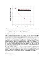
603 Hardware Specifications
23
and may float in the high-impedance state for relatively long periods of time. Since the 603 must continually
monitor these signals for snooping, this float condition may cause excessive power draw by the input
receivers on the 603. It is recommended that these signals be pulled up through weak (10 K
Ω
) pull-up
resistors or restored in some manner by the system. The snooped address and transfer attribute inputs are—
A[0–31], AP[0–3], TT[0–4], TBST, TSIZ[0–2], and GBL.
The data bus input receivers are normally turned off when no read operation is in progress and do not require
pull-up resistors on the data bus.
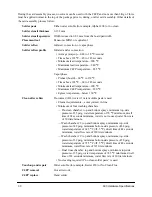
1.8.6 Thermal Management Information
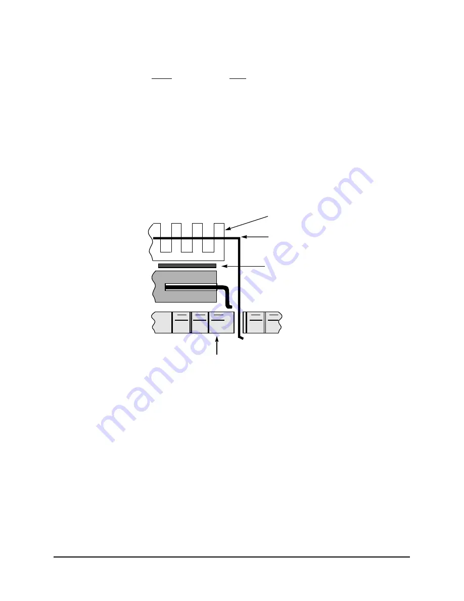
This section provides thermal management information for the ceramic quad-flat package for air-cooled
applications. Proper thermal control design is primarily dependent upon the system-level design—the heat
sink, airflow and thermal interface material. To reduce the die-junction temperature, heat sinks may be
attached to the package by several methods—adhesive or spring clip to holes in the printed-circuit board;
see Figure 13. This spring force should not exceed 5.5 pounds of force.
Figure 13. Package Exploded Cross-Sectional View with Several Heat Sink Options
The board designer can choose between several types of heat sinks to place on the 603. There are several
commercially-available heat sinks for the 603 provided by the following vendors:
Chip Coolers Inc.
800-227-0254 (USA/Canada)
333 Strawberry Field Rd.
401-739-7600
Warwick, RI 02887-6979
International Electronic Research Corporation (IERC)
818-842-7277
135 W. Magnolia Blvd.
Burbank, CA 91502
Thermalloy
214-243-4321
2021 W. Valley View Lane
P.O. Box 810839
Dallas, TX 75731
Adhesive
WB/CQFP Package
or
Thermal Interface Material
Heat Sink
Heat Sink
Clip
Printed-Circuit Board


