Motorola, Inc.
FCC ID: AZ492FT4843
TUNE UP PROCEDURE
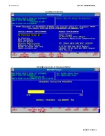
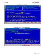
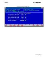
This exhibit contains the tune-up procedure as it will appear in the Radio Service Software (RSS)
manual.
The following adjustments comprise the total transmitter alignment:
1. Reference
Oscillator
2. VCO
3. Modulation
Compensation
4. Instantaneous Deviation Control and Audio Levels
5. RF Power Output
Note: All adjustments are factory pre-set and do not require alignment under normal operating conditions. In the
event alignment is needed, refer servicing to qualified radiotelephone personnel only.
TEST EQUIPMENT
Description
Recommended Model
1. Service Monitor
Motorola R-2600
2. PC with RSS
DOS Based
TRANSMITTER ALIGNMENT PROCEDURE
RSS Port
A 9-Pin D-Type connector is provided on the Station Control Module front panel to allow service
personnel to connect a PC loaded with the Radio Service Software (RSS) and perform programming and
maintenance tasks via this EIA-232 port. The following pages of this exhibit will show the important alignment
screens.
EXHIBIT 10B(1/4)


