


English
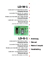
LD-G-1 / LD-W-1
Page 30
You can connect several LEDs in parallel to each output. In this case every
LED must have a series resistor of its own. If you connect several LEDs to
one output in series, only one series resistor is needed. The number of
LEDs connected in series to one output depends on the digital voltage.
You can determine the number of the LEDs that can be connected in
series to one output from the following formula:
(number of LEDs + 2) x 1,5 < digital voltage
Fixing the locomotive decoder
After completing all connections fix the locomotive decoder with double-
sided adhesive tape, for example.
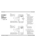
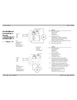
Using an NEM 652 interface connector
Contact Connection
Colour of cable
Connecting points
1
Motor connection 1
orange
X11
2
Lighting back (-)
yellow
X5
3
Not used or F1
green
X7
4
Power supply left
black
X1
5
Motor connection 2
grey
X12
6
Lighting front (-)
white
X4
7
Common conductor
for all functions (+)
blue
X3
8
Power supply right
red
X2
Some locomotives already have an NEM 652 interface connector
mounted. Using a convenient connecting plug you save disconnecting
the connections and you do not need to solder at the locomotive.
The list shows how to connect the contacts of the interface connector
to the connecting points of the locomotive decoder.
Setting the locomotive decoder
Setting the driving characteristics
Different driving characteristics can be fixed for the locomotve decoder:


