


LD-G-1 / LD-W-1
English
Page 29
!
!
!
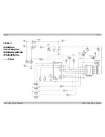
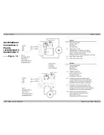
fig. 3a) or you must connect the second side of the lamps according to fig.
3b to the return conductor (point X3 on the front of the decoder).
Connect other accessories (e.g. smoke generator, cab lighting), which are
switched by the functions F1 to F4, to the points X7 to X10 (front of the
decoder). You can connect the second side of the accessories either to
the return conductor (point X3) or to locomotive ground. If connecting
the accessory to locomotive ground you must solder in a diode.
Caution:
The return conductor for all functions (point X3) must under no
circumstances be connected to locomotive ground. Possible short
circuit! The locomotive decoder will be damaged in operation.
Tip:
If the second side of the lamps is connected to locomotive ground
the lamps often flicker in operation. You can avoid the flickering of the
lamps if you connect the second side to the return conductor (point X3)
instead of locomotive ground.
Caution:
If you connect the loads to the return conductor for all functions (point
X3), the load must be insulated. The loads must not make contact with
metal parts of the locomotive. Possible short circuit! The locomotive
decoder will be damaged in operation.
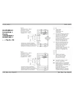
Connecting the LEDs
The function outputs of the locomotive decoder switch against decoder
ground. For that reason you must connect the cathode (-) of the LED to
the output of the relevant function.
Caution:
If you use light-emitting diodes (LEDs) you must always operate them
via a series resistor.
LEDs are available in many different models. There are LEDs with 2-5
mA, but also LEDs with 15-30 mA power consumption. The series
resistor limits the current flow of the LED and will need to be calculated
for each model. Ask for the max current rating when buying your LEDs.


