background image

October, 2004

6880309N15-A


1

5VA

AGND

5VA

AGND

R2

8

56

0

D2

1N

4148W

10

0KP

R2

10

0KP

R3

10

0KP

R5

C1

.1

C6

22pF

DGND

Q2

4401

10

0KP

R6

+10V

1M

R2

0

1M

R1

6

C3

.1

C2

.1

1M

R1

5

100KP

R120

5VA

1M

R2

1

150K

R121

2.2K

R11

+

10

uF

C1

5

10KP

R40

10KP

R38

68K

R13

C19

.01

100KP

R119

100KP

R50

1KP

R48

AGND

10

KP

R4

2

10KP

R43

5VA

68K

R44

1KP

R51

1KP

R49

5VA

5VA

15KP

R45

5VA

390K

R35

1M

R4

7

R57

1

R56

1

2.2K

R6

2

C3

0

.1

R67

1

TX AUD

R5

9

1

R6

0

1

R6

1

1

B-

HSSLV2

HSSLV1

1.5K

R2

7

D5

1N

4148W

C7

.1

56

0

R1

10

0KP

R4

R3

6

1K

P

5VA

1M

R3

3

1M

R7

AGND

1M

R8

6.8K

R19

2.2K

R12

R3

7

56

0

C47

.01

1M

R2

4

5VA

1M

R2

5

C1

1

.1

10KP

R32

RD RX AUD

JU4

SDR DOT

AGND

1.5K

R31

B-

33, LO ESR

+

C22

+

10uF

C16

C24

.1

NOT US

E

D

R

118

B-

6.8K

R58

B+

220, 25V

C28

+

ACC_RX

+

10

uF

C1

4

AC_MICLO

ACMICH

1.5K

R2

9

DM_MICLO

AGND

LMIC1

LMIC2

HSTIP2

HSTIP1

AGND

C1

2

.1

5VA

G7_ONHI

D3

1N

4148W

D4

1N

4148W

G4_ONHI

5VA

22K

R18

G3_ONHI

5VA

AGND

HS_SNS

SHEET 2

12

+

13

_

14

U1:D

3403

AGND

68K

R22

C4

.1

22K

R14

JU1

SDR DOT

1K

R10

22K

R9

5VA

EXTSPKR2

EXTSPKR1

R5

2

10

0

10VRMS Reference

10KP

R41

C13

22pF

G5_ONHI

G8_ONHI

CONRXAUD

600 mVRMS Reference
Filtered Audio

SPMUTE

R53

100

+

1uF

C20

100KP

R34

100KP

R26

ICLVLCONT

MIC SUM

G1_ONHI

1

2

3

4

L1

R54

1

R55

1

470, 16V

+

C23

5VA

100KP

R64

B-

C1

8

.1

AGND

1M

R4

6

R66

100KP

100KP

R63

1 W into 8 Ohms = 2.8VRMS

220, 25V

C29

+

C10

.1

DMICHI

ACC MIC AUD

D1

1N

4148W

1M

R3

0

1

IO

2

IO

13

CTRL

U4:A

4066

C8

.1

AGND

220K

R17

4

IO

3

IO

5

CTRL

U3:B

4066

3

+

2

-

1

U1:A

3403

Q1

4403

C9

.1

JU3

SDR DOT

JU2

SDR DOT

C5

.1

1

IO

2

IO

13

CTRL

U3:A

4066

11

IO

10

IO

12

CTRL

U3:D

4066

G6_ONHI

5

+

6

-

7

U2:B

3403

10KP

R39

3

+

2

-

1

U2:A

3403

4

IO

3

IO

5

CTRL

U4:B

4066

C2

1

10

0pF

10

+

9

-

8

U1:C

3403

B+

56.2KP

R23

10

+

9

-

8

U2:C

3403

.47, Film

C31

2

3

4

5

6

7

8

U6

TDA7056A

35 dB typical

+

10uF

C17

10K

POT3

HEADSET AUDIO LEVEL

+

1uF

C25

10K

POT2

ACC RX LEVEL

AGND

+

1u

F

C2

6

80 mVRMS Reference

100KP

R65

CNSTNT RXAUD

12

+

13

_

14

U2:D

3403

ICLVLCONT

LSPKR1

LSPKR2

3

+

2

-

1

U7:A

3403

C27

.1

POT1

10K

IC/MONITOR LEVEL

8

IO

9

IO

6

CTRL

U3:C

4066

8

IO

9

IO

6

CTRL

U4:C

4066

G2_ONHI

5

+

6

-

7

U1:B

3403

1 W into 16 Ohms =4 VRMS

TXAUD

ACCAUDGND

10

+

9

-

8

U7:C

3403

11

IO

10

IO

12

CTRL

U4:D

4066

1

BP

3

GND

14

VCC

2 IN+

6 IN-

8

OUT

U5

G = 34 dB

5

+

6

-

7

U7:B

3403

CDM Control Station Interface Module (CSIM), Audio Section

Содержание CDM1250

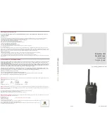
Страница 1: ...Professional Series Two Way Radio Service Installation Manual CDM Series Control Station ...

Страница 2: ... the SOFTWARE MOTOROLA SHALL NOT BE LIABLE FOR INCIDENTAL OR CONSEQUENTIAL DAMAGES ARISING FROM THE USE OF THIS SOFTWARE With respect to the U S Government if acquired under FAR policy 52 227 19 the SOFTWARE is provided with Restricted Rights and if acquired under DFARS policy 227 7202 then the SOFTWARE is provided only with the commercial rights of this Agreement This license is effective until t...

Страница 3: ...bility 1 Physical Description 1 CDM Control Station Housing 1 CDM Control Station Fan Assembly 1 CDM Control Station Power Supply 1 CDM Control Station Interface Circuit Boards 2 Cables 2 Preventive Maintenance 3 Visual Inspection 3 Periodic Cleaning 3 Section 2 CDM Control Station Operation Overview 1 General Description 1 Performance 1 General Specifications 1 Control Functions and Indicators 1 ...

Страница 4: ...udio Levels 1 Additional Considerations 2 Radio Control Head Speaker 2 Radio Programming Parameters 2 Desk Microphone 2 Basic Disassembly Assembly 2 Disassembling the CDM Control Station Housing 2 Removing the Housing Cover 2 Disassembling the Inner Chassis 2 Assembling the CDM Control Station Housing 3 Installing the Radio 3 Installing the Ground Stud 3 Connecting the Power Supply 3 Attaching the...

Страница 5: ...rnment for licensing rules NOTE In the United States of America the CDM Series radios may not legally be used as the transmit radio in a UHF 450 to 512 MHz repeater or base station application with 12 5 kHz channel spacing The 2 5 ppm fre quency stability capability of the radio does not meet the requirements of part 90 of the Rules and Regulations of the Federal Com munications Commission FCC In ...

Страница 6: ... CDN6288A Noise Canceling over the ear CDN6285A Over the ear w rear ear support for greater stability CDN6292A Noise canceling over the ear w rear ear support for greater stability CDN6287A Dual Ear CDN6294A Noise canceling dual ear Antennas RDD4527 150 158 MHz VHF 3 dB Gain RDE4556 450 470 MHz UHF 3 8 dB Gain General Accessories RRX4025 Type N Connector Coaxial In line Arrestor RRX4032 Tower Moun...

Страница 7: ...R2001 Service Monitor This monitor will substitute for items with an asterisk Frequency deviation meter and signal genera tor for wide range troubleshooting and align ment R1049 Digital Multimeter Two meters recommended for ac dc voltage and current measurements S1100 Audio Oscillator 67 to 200 Hz tones Used with service monitor for injection of PL tones S1053 SKN6009 SKN6001 AC Voltmeter Power Ca...

Страница 8: ...vi 6880309N15 A October 2004 Foreword CDM Control Station Test Equipment ...

Страница 9: ...bile Radio Compatibility The CDM Control Station was designed to incorporate the CDM750 CDM1250 or CDM1550 mobile radios Physical Description The following paragraphs describe the physical characteris tics of the Control Station CDM Control Station Housing CDM Control Station Fan Assembly CDM Control Station Power Supply CDM Control Station Interface Circuit Boards CDM Control Station Housing The ...

Страница 10: ... mobile antenna kits Do not use RG58A U as the coaxial cable that connects the antenna con nector of the Control Station to the antenna The rather small size of the RG58A U can introduce excessive losses in the system that will decrease the effective range of the Control Station Substitute RG400 U for short lengths and RG214 U or 1 2 inch hardline for the longer lengths If the hardline is used con...

Страница 11: ...y clean smudges and grime from the exterior housing Use a soft non abrasive cloth moistened in a mild soap and water solution Rinse the surface using a second cloth moistened in clean water and clean any dirt or debris from the fan grill type N male connector 2884476G01 type N 1 2 hardline male TDN6677 type N 1 2 hardline female TDN6678 RG58A U coaxial cable 3000475378 RG400 U coaxial cable 308417...

Страница 12: ...1 4 6880309N15 A October 2004 Introduction to the CDM Control Station CDM Control Station Preventive Maintenance ...

Страница 13: ... the following sources front panel Transmit but ton desk microphone PTT headset PTT or PTT from an accessory device The Transmit LED located above the Transmit button on the front panel is illuminated whenever the transmitter is keyed in this manner Monitor Before transmitting the selected channel should be checked for co channel activity by using the Monitor function RX squelch is disabled when M...

Страница 14: ...isabled by switch programming Volume of radio RX audio is adjustable using the control knob on the mobile s control head Volume of the accessory intercom transmit audio is adjustable via a pot located on the back panel of the inner chassis Headset volume of radio RX audio is adjustable via a pot located on the back panel of the inner chassis NOTE Accessory parallel audio is routed only to the spea...

Страница 15: ...trol Station is configured by default to use a desk microphone DIP switch 6 should be in the ON position Headset The Control Station can be configured to operate with a headset DIP switch 7 should be in the ON position Internal Microphone The Control Station comes equipped with an internal microphone intended for use in low noise environ ments The local microphone is active anytime the front panel...

Страница 16: ...2 4 6880309N15 A October 2004 CDM Control Station Operation CDM Control Station Operator Instructions ...

Страница 17: ...io port This feature is to enable Intercom for desk sets that are not equipped with the ability to monitor TX audio Switch 4 Mute Accessory RX Audio During Intercom When switch 4 is on radio RX audio to the accessory RX Audio line will be muted during Intercom pushing the front panel Intercom button Switch 5 Intercom Audio From Local Mic When switch 5 is on the selected mic source for base station...

Страница 18: ...ontrol circuitry installed To install the radio and configure the unit the Con trol Station may have to be completely disassembled With the Control Station disassembled you can begin to install the radio and configure the Interface Module before reassembling the housing Before beginning installation remove all items from the packing container and check them against the items refer enced in one of ...

Страница 19: ...he control head is positioned in the opening The inner chassis uses a slotted hole that allows the installer to adjust depth of the radio in the chassis 2 If you are installing the optional Internal RF Cable order part number 3080517U10 3 Remove the nut and lockwasher from the cable 4 Insert the type N female bulkhead connector into the Antenna D hole located on the enclosure back panel beneath th...

Страница 20: ...nd ensure all cables are inside of the unit 4 Using a T15 Torx driver secure the cover to the base with the six 6 TT 3 5mm pan head Taptite screws removed in Step 3 Removing the Housing Cover Field Installation To operate the Control Station the AC line cord antenna feed line ground cable and optional accessory cable must exit from the rear of the unit In addition you must connect all of the neces...

Страница 21: ...tation 1 9 0180305K03 ASSEMBLY PCB Key Panel CDM 1 Control Station 10 7580384N51 ASSEMBLY Speaker 1 11 0180305K04 ASSEMBLY PCB Interface Module 1 CDM Control Station 12 01 80557U01 FAN with Connector 1 13 13 83852R01 GRILLE Fan 1 14 3080517U10 RF CABLE Internal Mini UHF Male to 1 N Bulkhead Female 15 inches 15 42 85866M01 CLIP Thermal Switch 1 16 30 80137S02 CABLE Internal Radio Interface 1 17 30 ...

Страница 22: ...E Housing CDM Control Station 1 7 0180305K02 ASSEMBlY PCB Audio Panel CDM 1 Control Station 8 75 80384N51 KEYPAD CDM Control Station 1 9 0180305K03 ASSEMBLY PCB Key Panel CDM 1 Control Station 10 7580384N51 ASSEMBLY Speaker 1 11 0180305K04 ASSEMBLY PCB Interface Module 1 CDM Control Station 12 01 80557U01 FAN with Connector 1 13 13 83852R01 GRILLE Fan 1 14 3080517U10 RF CABLE Internal Mini UHF Mal...

Страница 23: ...justment Speaker audio is muted by signal SPMUTE U6 pin 5 during PTT or during an accessory transmit if switch 8 is on Constant level receiver audio from the radio P3 pin 11 is routed to the accessory device through amplifiers U2C and U5 It is also routed to the headset earpiece through POT3 and amplifier U7A B Digital functions Mic Selection The headset mic is enabled whenever headset PTT is acti...

Страница 24: ...4 2 6880309N15 A October 2004 CDM Control Station Theory of Operation CDM Control Station Digital functions ...

Страница 25: ...ordingly Interface Module settings on pages 3 1 and page 3 12 Desk Mic does not provide Intercom audio The desk mic must have a jumper in stalled to allow proper operation Desk Microphone on page 3 2 Receive Audio is distorted Ensure that Accessory Configuration RX Audio on the radio is set for Fil tered Audio Radio Programming Parameters on page 3 2 Unable to communicate with field ra dios Ensure...

Страница 26: ...5 2 6880309N15 A October 2004 CDM Control Station Troubleshooting CDM Control Station ...

Страница 27: ...0KP R41 C13 22pF G5_ONHI G8_ONHI CONRXAUD 600 mVRMS Reference Filtered Audio SPMUTE R53 100 1uF C20 100KP R34 100KP R26 ICLVLCONT MIC SUM G1_ONHI 1 2 3 4 L1 R54 1 R55 1 470 16V C 23 5VA 100KP R64 B C18 1 AGND 1M R46 R66 100KP 100KP R63 1 W into 8 Ohms 2 8VRMS 220 25V C29 C10 1 DMICHI ACC MIC AUD D1 1N4148W 1M R30 1 IO 2 IO 13 CTRL U4 A 4066 C8 1 AGND 220K R17 4 IO 3 IO 5 CTRL U3 B 4066 3 2 1 U1 A ...

Страница 28: ...LIC C35 1 SUPERON 3 4 U9 B ACPTT 10V ACCMON 100KP R69 1 2 U8 A 4 7K R124 DSMON DSKPTT 1 2 U11 A HSPTT 11 10 U9 E C41 1 HS_SNS DGND D28 1N4148W 3 4 U11 B 10V LCLPTT 10V D22 1N4148W HS_SNS 10V 3 4 U10 B D17 1N4148W HS_SNS 10V D13 1N4148W 10V 1 2 U10 A G7_ONHI G8_ONHI DGND 10V G6_ONHI G5_ONHI D30 1N4148W G4_ONHI D27 1N4148W G3_ONHI D18 1N4148W G2_ONHI G1_ONHI AUDIO GATING FUNCTIONS TO SHEET 1 AGND B ...

Страница 29: ...1 P3 9 P3 7 P3 5 P3 4 P3 2 P3 16 SW_BAT SW_BAT PGND TXAUD EXTSPKR2 ACCAUDGND ACMICH ACC_RX P4 15 P4 13 P4 12 P4 11 P4 9 P4 7 P4 5 P4 4 P4 2 P4 16 P4 1 P3 14 P3 10 P3 8 P3 6 P3 3 P3 1 IGN_DET CONRXAUD RXMON TXPTT EXTSPKR1 ACCPTT ACCMON P4 14 P4 10 P4 8 P4 6 P4 3 R117 1KP R113 1KP P2 10 P2 11 P2 9 P2 8 P2 6 P2 5 P2 3 P2 2 CBL2 11 CBL2 10 CBL2 8 CBL2 9 CBL2 6 CBL2 5 CBL2 3 CBL2 2 R116 1KP RED LED2 P2...

Страница 30: ...4 6880309N15 A October 2004 CDM Control Station Circuit Board Details CDM Control Station Audio Panel CSAP CDM Control Station Key Panel CSKP CDM Control Station Interface Module CSIM ...

Страница 31: ......

Страница 32: ...ogo are registered in the U S Patent and Trademark Office All other product or service names are the property of their respective owners Motorola Inc 2004 All rights reserved Printed in U S A Motorola Inc 8000 West Sunrise Boulevard Ft Lauderdale FL 33322 ...

Отзывы: