2/6/98
Issue 1.0
37
Troubleshooting
#3 NPU Repair Procedure
No 13MHz reference clock signal at pin 57 of U201.
The components that will most likely affect the 13MHz reference clock are C201,
C203, CR201, U201, and Y201. Check that the mentioned components are not physi-
cally damaged, have no dry joints, and are positioned correctly.
If none of the mentioned problems are apparent, take measurements on the defective
PCB to decipher which component(s) you feel should be replaced, or replace the
following components in the order shown:
1st - Replace Y201
2nd - Replace C203
3rd - Replace CR201
4th - Replace C201
• Check the PCB after each component change to verify fault elimination.
If replacing the above components does not eliminate the fault, return the PCB to a
Motorola Hi Tech Center.
#4 NPU Repair Procedure
No 13MHz reference clock signal at pin 17 of U703.
• Review the audio logic block diagram which shows the path of the 13MHz clock.
• Confirm 13MHz clock signal presence at U703, pin 37.
• Confirm 13MHz clock signal presence at U500, pin 40.
• Confirm 13MHz clock signal presence at U701 pin 38.
If the 13MHz clock enters U703 but does not appear at the output (pin 37), inspect
the chip for physical damage, dry joints and correct position. If none of the
mentioned problems are apparent, ensure that the supply voltage to the chip is
present (see appropriate chip diagram). If present, replace the chip.
If the clock signal is present at U703 pin 37, but not present at any of the other afore-
mentioned chips, ohm the path from that chip back to U703 pin 37. If the trace is
functional, check the chip in question for supply voltage.
If no supply voltage to the chip, trace its B+ path and/or replace the chip. If after
replacing all of the above components the fault is not eliminated, return the PCB to
a Motorola Hi Tech Center.
Содержание cd 160
Страница 7: ...viii Issue 1 0 2 6 98 StarTAC 160 GSM ...
Страница 9: ...2 Issue 1 0 2 6 98 StarTAC 160 GSM ...
Страница 13: ...6 Issue 1 0 2 6 98 StarTAC 160 GSM ...
Страница 17: ...10 Issue 1 0 2 6 98 StarTAC 160 GSM ...
Страница 25: ...18 Issue 1 0 2 6 98 StarTAC 160 GSM ...
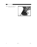
Страница 31: ...24 Issue 1 0 2 6 98 StarTAC 160 GSM Step 4 Lift the white display clip off the transceiver board ...
Страница 65: ...58 Issue 1 0 2 6 98 StarTAC 160 GSM Figure 27 StarTAC Parts Illustration ...
Страница 67: ...60 Issue 1 0 2 6 98 StarTAC 160 GSM ...
Страница 75: ...68 2 6 98 ...

