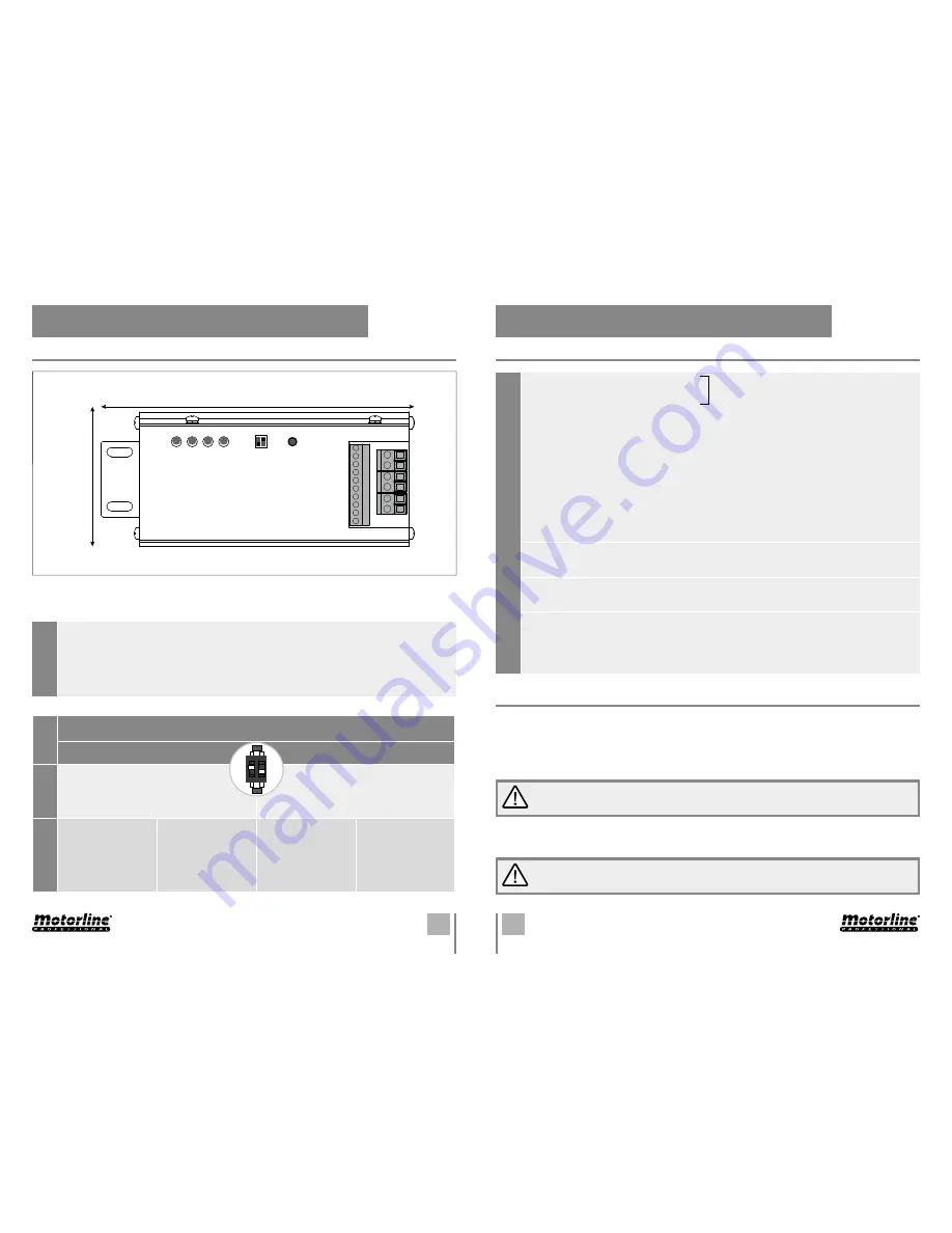
11A
11B
EN
EN
06. THE CONTROL BOARD
TECHNICAL CHARACTERISTICS
06. THE CONTROL BOARD
TECHNICAL CHARACTERISTICS
Conet
or
es
6 •
Two singular doors connection - Entrance
7 •
Two singular doors connection - Exit
8 •
Common
9 •
Photocells (Aperture)
- Connection (
N.O
) of a safety sensor for the opening. If the terminal
closes during the aperture, the door will stop opening and will start to close.
10 •
Common
11 • Photocells (Closure)
- Connection (
N.C
) of a safety sensor for the closure. If the terminal open
sduring closing, the door will reverse the movement.
12 •
Common
13 •
START (P.P.)
- Push button to open the door (
N.A
).
14 •
COM
15 •
Empty
16 •
Eletric lock power supply output (+12V DC)
17 •
Eletric lock power supply output (-12V DC, 600mA)
18 • Accessories power supply:
+15V DC , 500mA.
19 • Accessories power supply:
-15V DC
20 •
Battery input 24V (+)
21 •
0V. If the terminal is connected with a 24V additional battery, when the 230V AC fails, the
automation will continue to operate.
Note •
With the 230V AC power supply ON, the terminal
output voltage can be higher or lower than 24V.
PROGRAMMING
01 •
Make sure that all connections between components and control board are made according
to the manual (see the schemes in p. 4, 5 and 6).
02 •
Before connecting to the eletric current, check if there is some sort of obstacle that hinders
the normal operation of the door and if the stopper is well placed.
03 •
Put the K2 and the K1 in the desired position according
to the dipper board from the page 11A.
04 •
Turn on the electric current. The door will have the following behavior:
Slowy closes → Slowly opens → Closes (to memorise the position) and stays in normal operation
after finishing the cycle.
•
Before connecting the automation to the power supply, you must have the stopper
installed so that the control board can recognize the course.
•
When the door is in normal operation, the opening angle will reduce 2 degrees
therefore, it does not need to touch the stopper during all cycles.
Pot
entiomet
er
s
1 •
Opening speed
2 •
Closing speed
3 •
Delay time between motor nº1 and motor nº2 (when installed 2 motors)
4 •
Pause time
Dippers
ON
OFF
K1
Magnetic lock
The output is continuously
activated when the door is closed.
Normal lock
When the opening is triggered,
the output receives an impulse for 3
seconds to open the latch.
K2
Opening orientation:
RIGHT
Opening direction:
INSIDE
Opening orientation:
LEFT
Opening direction:
OUTSIDE
Opening orientation:
LEFT
Opening direction:
INSIDE
Opening orientation:
RIGHT
Opening direction:
OUTSIDE
OFF
K1 K2
ON
16
152mm
56.5mm
17
18
19
20
21
1
6
7
8
9
10
11
12
13
14
15
2
3
4
K1 K2
Interlocking between 2 singular doors


