(continued)
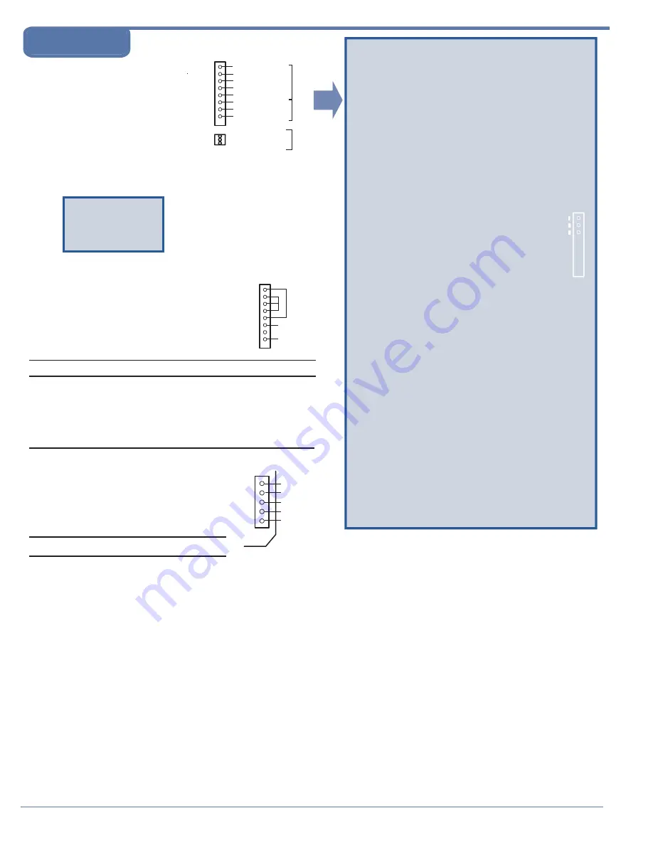
8. Connect EZServo to motor.
BLDC Motors: Connect servo motor
and Hall sensors to the eight pins of
the motor connector as shown in
diagram: (See Wiring Note on
preceding page and Hall sensor
phasing instructions on this page.)
On SV23 models, use 3-pin screw
terminal for high-current motors.
Brush motor connections: Connect brush servo motor to the eight
pins of the motor connector as shown in diagram:
(See Wiring Note on preceding page.)
9.
Ensure power is ON.
10. Test velocity function:
Issue command /1N0R to tell the board there is no encoder.
Issue command /1P0R or /1D0R endless move; then confirm response.
Issue command such as /1V10R to change speed; then confirm
response. (Hall sensors provide feedback for velocity control.)
11. If only velocity control is required, skip this step. If position
control is required, turn power OFF.
Then connect encoder to 5-pin connector
as shown in diagram:
(See Wiring Note
on preceding page
.)
12. Turn power ON.
13. Issue command /1P1000. The motor will move 1000 steps in
the positive direction.
If motor spins without stopping, reverse the CHA and CHB
connections.
You're on your way!
For other commands and hookups,
see the full command set and wiring diagram on our website.
MOTOR -
MOTOR +
GROUND
CHAN B
+5V ENCODER
POWER
CHAN A
INDEX
CAUTION!
Always turn off power before
connecting or disconnecting
motor to avoid damaging
circuit board.
NOTE: If you send your
motor to us, we will be
happy to work out the
correct Hall sensor
phasing for you.
CAUTION!
Always turn off power before
connecting or disconnecting
motor to avoid damaging
circuit board.
NOTE
On SV17, Hall Sensor
power is +15V. If +5V is
needed, obtain from
encoder connector pin 4.
Motor Tuning (BLDC motors)
If motor behavior is oscillatory:
Increase the value of the differential gain constant, for
example /1y3000R.
If oscillatory behavior continues, motor is noisy, and
encoder ticks can be heard, reduce both the proportional
and the differential constants until satisfactory
performance is obtained. For example, /1w250y500R
works well, especially with high (4000) line-count
encoders.
(The larger the line count, the smaller the w, x, and y
values.)
1
1
2
2
3
3
Hall Sensor Phasing (BLDC motors)
This is a trial-and-error method for finding the correct
hookup for your Hall sensor. (The correct hookup for
many Hall sensors can be found in the EZSV17 or
EZSV23 wiring diagram on our Web site.)
NOTE: For Hall sensor phasing by trial
and error, you MUST use a current-limited
lab supply set to the lesser value of 1/2A or
1/4 of the maximum current rating of the motor.
1. With power OFF and the encoder disconnected,
wire Hall sensors to pins 1, 2, and 3 in any order.
2. Set the current limit low by issuing command
/1m30R.
3. Do the following as you try each of the 6 possible
wiring combinations (123,132, 213, 231, 312,
321): ALWAYS DISCONNECT POWER BEFORE
CHANGING WIRES
Issue command /1A1000R. The motor
should spin smoothly in one direction for
about 5 seconds and stop
.
While the motor spins, hold its shaft lightly
and observe any "dead spots" that you feel.
DO THIS ONLY IF YOU CAN DO IT SAFELY!
Four combinations will produce dead spots or
positions at which the rotor locks.
One combination will produce dead spots or
positions at which the rotor locks that are less
obvious.
One combination will produce very smooth motion
with no dead spots or rotor locking points.This is
the correct wiring combination for your Hall
sensors.
NOTE: Don't switch power wires to the motor;
only switch Hall sensor wires.
All Motion
www.allmotion.com
5501 Del Oro Court, San Jose, CA 95124 Telephone 408.460.1345 Email
E Z S t a r t
Hall
Sensors
1
2
3
4
5
6
7
8
Motor
Use for
motors 3A
or higher
on SV23
HALL C
HALL SENSOR POWER
HALL SENSOR GROUND
PHASE A DRIVER
HALL A
HALL B
PHASE C DRIVER
PHASE B DRIVER
PHASE A DRIVER
PHASE C DRIVER
PHASE B DRIVER
Starting up


