


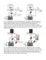


Fig. 4 – Example with positive grounding for a ProStar MPPT system.
Positive Ground for the Telecom Load
In order to keep the telecom load grounded during operation the positive ground has to be connected to
the battery circuit or the load circuit as shown in Fig. 1 or Fig. 2. If it is grounded on the PV array circuit
the battery and load will not have a positive ground. Morningstar controllers that include load control
have a common negative so when it disconnects the load the load will no longer be grounded. However,
the telecom equipment should not require a positive ground when disconnected. If for some reason this
is considered a problem grounding the load circuit is an option.
Chassis/Enclosure Ground
For Morningstar controllers the chassis is isolated from the DC circuits of the controller. Therefore, the
chassis can be grounded the same for a positive ground system as it is for a negative grounded system.
Grounding the chassis is required by code in many jurisdictions. Surge protection devices include a
connection to the equipment ground in order to function properly to limit voltage surges from nearby
lightning strikes. Many Morningstar controllers include a chassis ground terminal. If it doesn't it is
possible to wire a equipment grounding conductor directly to the chassis. Please see the product manual
for more information about equipment grounding and follow local electrical code equipment ground
requirements.
Disconnect and overcurrent protection with Communications Wiring
The NEC and many jurisdictions allow for using a disconnect and overcurrent protection on the
ungrounded conductor. Therefore, single-pole battery breakers, switches or fuses may be installed on
the negative power conductors. However, this may not be an option with some systems depending on
the communications configuration.


