

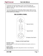


Page 10
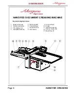
HAND FED CREASING
Setting the Adjustable Side Lay
Place the paper stack on to the loading table and slide up to the fixed side lay.
Position the adjustable side lay up towards the paper stack, allow a gap of approx.
0.5mm (1/64 inch) between the paper and the side lay.
Setting the Roller Tilt Mechanism
The roller tilt mechanism has been designed to compensate for when the creasing
position on the sheet is not square. This could be due to an inaccuracy in the media or if
the roller tilt mechanism has been incorrectly set. The mechanism will be set to zero
(square) when the machine is supplied.
To set the mechanism, unlock the roller tilt knob located below the roller tilting handle by
turning anti-clockwise. Move the roller tilt handle left or right in order to compensate for
any inaccuracy. When the position is set, ensure to lock the roller tilt knob before
operating the machine. Repeat the above procedure until the creasing position is square.
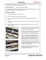
Setting the positions of drive wheels and hubs
It is important that the drive wheels and drive hubs on the roller shafts are arranged evenly
across the width of the media being creased. This is done to ensure that the media is
accurately driven and supported through the rollers.
The drive wheels and hubs are fixed to the rollers by means of a grub screw. To locate
this grub screw the rollers can be rotated by operating the motor manually.
DO NOT ROTATE THE DRIVE ROLLERS BY HAND.
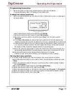
To operate the motors manually, switch the machine ‘on’ at the Emergency Stop switch.
Following the arrows on the display unit, move the selection switch to the left to select
Tools
, the display will now show the Tools sub-menu. Press the system switch down and
then move the selection switch to the left or to the right, to rotate the rollers in short pulses.
This procedure should be repeated when installing perforating blades and anvils onto the
drive wheels and hubs.
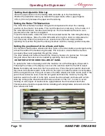
FIG 10.1
Lift the exit guard to see if the grub screws in the drive wheels and hubs can be seen. If the
grub screws cannot be seen, lower the exit guard and rotate the rollers by moving the
selection switch to the left or to the right. Loosen the drive wheels and hubs with a 2mm
allen key. Arrange the drive wheels and hubs as shown in FIG 10.1. In order to avoid
marking on some types of media ensure a gap between the drive wheels and hubs.
Operating the Digicreaser
Содержание DigiCreaser
Страница 5: ...Page 5 SYSTEM BLANK PAGE DigiCreaser ...
Страница 29: ...Page 29 SYSTEM DigiCreaser ...


