


*REFER TO CHECK SHEET FIRST
1/99
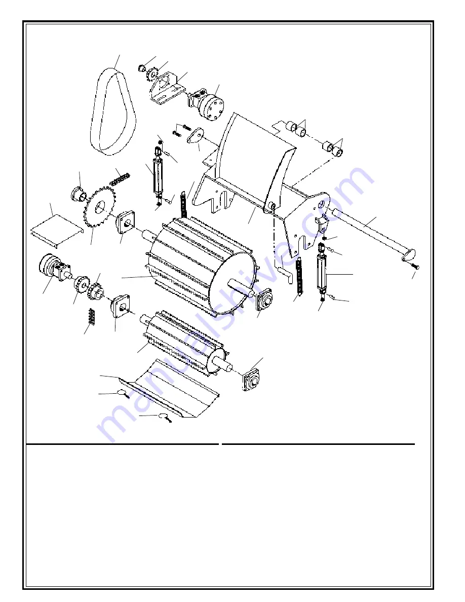
INFEED COMPONENTS
ITEM
QTY.
PART NO.
DESCRIPTION
1
1
40188-452
Feed Wheel
1 a
30278-452
Feed Wheel Teeth
2
2
23918-622
Bearing
3
2
24741-621
Spring
4
1
40201-452
Yoke Assembly
5
1
40186-462
Pivot Shaft
6
4
23131-113
Bushing
7
1
31029-462
Washer
8
3
21624-353
Bolt
9
1
26737-207
Hydraulic Motor
10
1
30480-701
Motor Mount
11
1
24264-753
Sprocket
12
1
24132-103
Bushing
13
1
40182-452
Chain Guard
14
24251-026
Roller Chain
ITEM
QTY.
PART NO.
DESCRIPTION
15
1
24264-837
Sprocket
16
1
24132-212
Bushing
17
2
26816-119
Cylinder
18
4
26816-538
Pin
19
4
30784-901
Bushing
20
2
31030-462
Yoke Lock Pin
21
2
23918-629
Bearing
22
1
40215-452
Bottom Feedwheel
23
1
24333-245
Chain Coupler Half
24
1
24333-002
Roller Chain
25
1
24333-247
Chain Coupler Half
26
1
26737-204
Hydraulic Motor
27
1
31387-462
Chain Coupler Cover
28
1
40216-452
Cleanout Door
29
2
21129-054
Door Clips
6
6
5
1 8
1 9
1 7
1 8
1 9
2
1 6
3
1 4
1 8
1 9
1 9
3
9
1 1
1 2
7
8
8
2 0
1
2 1
2 4
2 1
2 3
2 5
2 6
2
1 5
2 7
1 7
1 8
1 0
1 3
2 2
2 8
2 9
2 9
4
3 3
Содержание TORNADO 13
Страница 1: ... REFER TO CHECK SHEET FIRST 1 99 76340 241 1 99 Manufactured By Morbark Inc ...
Страница 2: ... REFER TO CHECK SHEET FIRST 1 99 ...
Страница 27: ... REFER TO CHECK SHEET FIRST 1 99 SAFETY MAINTENANCE BASIC ELEMENT SERVICE PRECAUTIONS to enter element 24 ...
Страница 31: ... REFER TO CHECK SHEET FIRST 1 99 ELECTRICAL DIAGRAM ADJUSTING THE AUTO FEED 28 200 250 ...
Страница 46: ... REFER TO CHECK SHEET FIRST 1 99 HYDRAULIC SCHEMATIC 43 ...
Страница 48: ... REFER TO CHECK SHEET FIRST 1 99 WARRANTY 45 ...


