30
Rev. 1.1
0004102014
SS03/05/10-S/Q/C Hardware Manual
400-820-9661
4 Mounting the Drive
Use the M3 or M4 screw to mount the SS series drive .The drive should be securely fastened to a
VPRRWKÀDWPHWDOVXUIDFHWKHZLOOKHOSFRQGXFWKHDWDZD\IURPWKHFKDVVLV,IWKLVLVQRWSRVVLEOH
IRUFHGDLUÀRZIURPDIDQPD\EHUHTXLUHGWRSUHYHQWWKHGULYHIURPRYHUKHDWLQJ
1HYHUXVHWKHGULYHLQDSODFHZKHUHWKHUHLVQRDLUÀRZRUWKHVXUURXQGLQJDLULV
more than 40
ć
.
Never put the drive where it can get wet or where metal or other electrically
conductive particle particles can get on the circuity.
$OZD\VSURYLGHDLUÀRZDURXQGWKHGULYH:KHQPRXQWLQJPXOWLSOH66GULYHVQHDU
each other, maintain at least 1.5cm of space between drives.
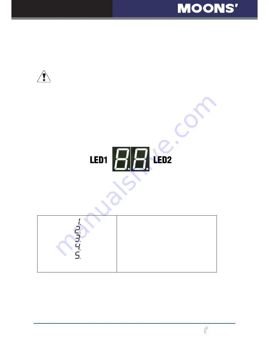
5 LED Display
SS series have two 7-segments LED,which is used to display operation mode ,error code ,bus
address and communication baud rate.
LED1 is used to indicate operation mode and error code. When drive has no error ,LED1 is
VROLGRQWRLQGLFDWHRSHUDWLRQPRGH:KHQGULYHKDVHUURU/('ZLOOÀDVKDWDVHFRQGUDWHWR
indicate error code. The dot point of LED1 is to indicate whether the drive is enabled. When the
dot point is on ,the drive is enabled When the dot point is off,the drive is disabled.
5.1 Operation Mode
Ɣ
Ɣ
Ɣ
1:CM1(Commanded Torque Mode)
2:CM2(Analog Torque Mode)
3:CM11~14(Analog Velocity Mode)
4:CM15~18(Velocity Mode)
5:CM10(Commanded Torque Mode)
6:CM7(Digital Position Mode)
7:CM21(Point to Point Mode)
8:CM22(Analog Position Mode)
Содержание SS03-C-C
Страница 1: ...Rev 1 1 0004102014 SS S Q C Step Servo Drive Hardware Manual SHANGHAI AMP MOONSýAUTOMATION CO LTD ...
Страница 5: ...5 Rev 1 1 0004102014 400 820 9661 SS03 05 10 S Q C Hardware Manual 1 2 Block Diagram ...
Страница 6: ...6 Rev 1 1 0004102014 SS03 05 10 S Q C Hardware Manual 400 820 9661 ...


