Monticello Flying Club Pilot Transition Manual: Mooney M20F
Page 13 of 42
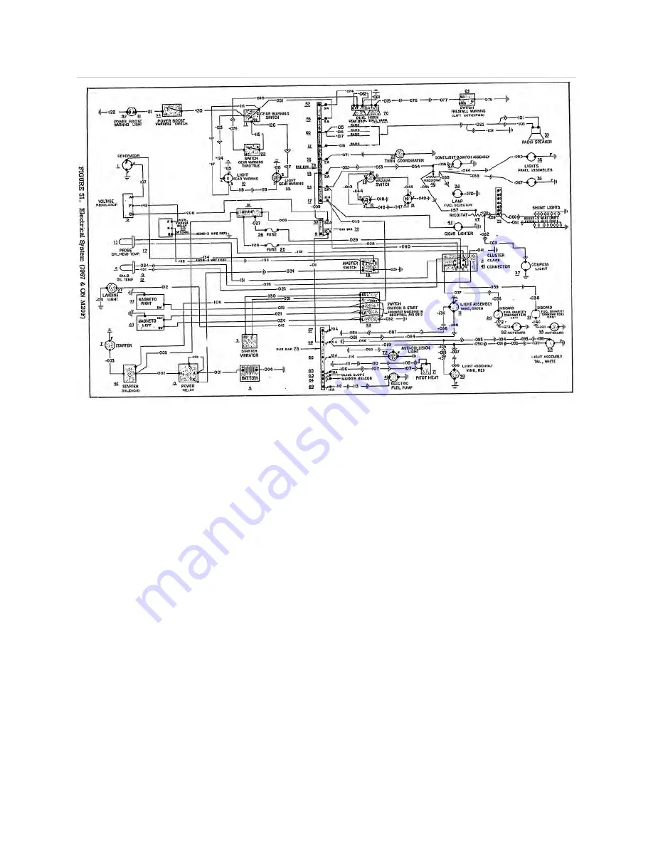
Electrical System Schematic
F
UEL
S
YSTEM
The fuel system has internally sealed, integral wing tanks in the forward, inboard section
of each wing. Because of frequent leaks in this type of tank system, our aircraft had fuel bladders
added to the tanks. This prevents leaks, but reduced the fuel capacity by 9.2 gallons, resulting in
a
total capacity (now) of 54.8 gallons
, and added 26 pounds of weight. Additionally, there have
been some problems with water getting into these bladder systems so
an AD was issued
requiring each tank to be sumped for 4 seconds each.
Vents at the aft outboard corner of each tank extend downward through the lower wing
surface. There is a piece of metal in front of each vent to reduce the risk of ice forming in the
vent. These tank vents are also designed to be a tube-within-a-tube, which helps to prevent
freezing. These fuel vents allow for overflow and fuel tank ventilation, and they should be
checked for obstruction during pre-flight inspection.
Fuel sump drains are located at the lowest point in each tank. Fuel feeds from either tank
to a valve through a gascolator integral with valve and low-point drain. The selector valve (see
picture in Chapter 5) is located between the pilot’s legs along with a selector sump ring that is
pulled up to drain the sump for each tank at the selector. This point is the lowest point in the fuel
system. The selector goes from ‘left’ to ‘off’ (pointing at pilot) to ‘right’. While you do have to
go through ‘off’ position to switch tanks, there is sufficient fuel in the lines to prevent this from
stopping the engine as long as it is done in a reasonable amount of time.
The electric fuel pump is in the bottom left forward section of the fuselage just aft of the
firewall. Fuel feeds from either tank through the selector valve to the electric pump then to the


