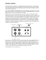
A. THE AUDIO GENERATORS
995
904A
902
902
921A
921B
923
921
911
911
921B
MIXER
REV
CONTROLLERS
TRUNK
907A
5
5
0
5
5
0
0
0
8’
50
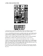
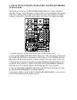
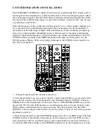
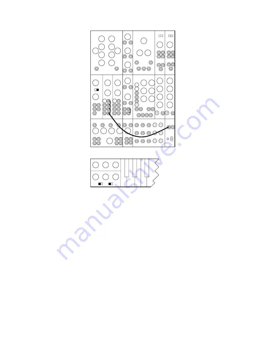
1. Turn on the power switch. This supplies power to the entire instrument. Turn all controls
and switches to the positions shown in the drawing. Turn on the monitor amplifier.
2. Locate a 921B OSCILLATOR. Patch from the RECTANGULAR output to TRUNK LINE
1. The oscillator’s rectangular waveform output is being fed directly to the monitor system.
Adjust the monitor amplifier gain so that the tone sounds comfortably loud.
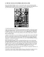
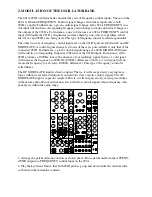
3. Remove patch cord from the RECTANGULAR output and insert it in the SAWTOOTH,
TRIANGULAR, and SINE. Notice the different tone qualities of each waveform.
The Synthesizer 15 contains 3 modules (921 Series) that generate these 4 wave forms.
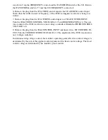
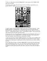
4. Remove the patch cord from the 921B OSCILLATOR and plug it into the WHITE NOISE
output of the 923 NOISE SOURCE. This signal contains all audible frequencies in a random
mixture. Next plug the patch cord into the PINK NOISE output. This signal has more low fre-
quency and less high frequency content than white noise signal.
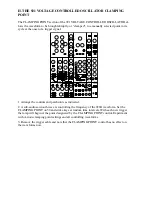
Every sound source on the instrument has now been heard in its raw form. In the remaining
exercises, these signals will be mixed, modified, and controlled by the remaining modules of
the system.


