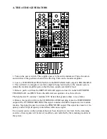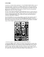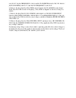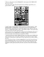
3. Now move the patchcord from the FREQUENCY control input to the DC MODULATE
input on the left 921B.
4. Play the keyboard. Notice that only the pitch of the left 921B goes up and down in re-
sponse to the 911’s output.
995
904A
902
902
921A
921B
923
921
911
911
921B
MIXER
REV
CONTROLLERS
TRUNK
907A
0
8’
0
50
Sq
0
4’
5
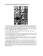
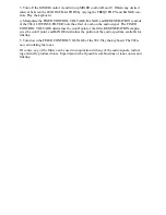
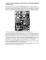
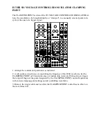
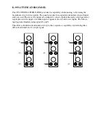
5. Set the controls on the 921 OSCILLATOR as shown. Run a patchcord from the "-" AUX-
ILIARY OUTPUT to a FREQUENCY control input on the 921A. Set the AUXILIARY
OUTPUT LEVEL control on the 921 so that the pitch jumps an octave. Then move the cord
from the "-" AUXILIARY OUTPUT to the "+" AUXILIARY OUTPUT. Notice that the pitch
jump is still an octave, but in the opposite direction.
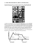
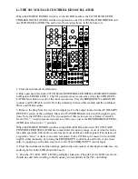
6. Repeat the above step, but with the patchcord plugged into the DC MODULATE input on
the left 921B instead of the FREQUENCY control input on the 921A. Note that the down-
ward interval jump is much greater than the upward interval JUMP.
7. Move the patchcord from the DC MODULATE input on the 921B to the AC MODULATE
input. Notice that the effect of the square modulating wave on the pitch is radically changed,
so that after each pitch jump, the pitch quickly returns to that which exists without a modulat-
ing signal.
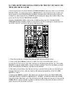
8. Leave the patchcord in place and turn the FREQUENCY control on the 921 full clockwise.
The rapid modulation produces a new tone color with non-harmonic partials. Because of the
linear mode of modulation, the average frequency of the audio signal is unchanged by the
modulation, and the apparent pitch of the new timbre is the same as that of the unmodulated
signal.

