background image

Modulator section.
   The MIX knob crossfades from the direct (unmodulated) signal to the signal from the

ring modulator output. You hear only the direct signal when the knob is
counterclockwise, and only the ring-modulated signal when the knob is clockwise. You
crossfade smoothly from one signal to the other as you turn the knob.
   The FREQUENCY knob and the LO-HI switch determine the frequency of the carrier

oscillator. The FREQUENCY knob has two calibration ranges: 0.6 Hz to 80 Hz, and 30 Hz
to 4 kHz. The LO-HI switch setting determines which range is on.
Audio Input Level
   The DRIVE control and the LEVEL light are part of the audio input level circuitry.

   The DRIVE control adjusts the input gain. With this control you can set the right input
gain for virtually any instrument or line-level signal source.  Turn this control
counterclockwise for strong input signals, and clockwise for weaker sound sources. The
DRIVE control is always active, even when the MF-102 is in BYPASS mode.
   The LEVEL light tells how strong the input signal is after being adjusted by the DRIVE

control. As the signal level increases, the light goes from off, to green, to yellow, and
finally to red. Very weak signals do not light up this light at all. When the light is green,
the signal is below the level that results in audible distortion. When the light is yellow,
some low order distortion may be audible, giving the sound a subtle warm analog

quality.  When the signal is strong enough to drive the light into the red, the distortion at
the output becomes stronger and more distinctly audible. Watch this light when you set
the DRIVE control for the desired effect.

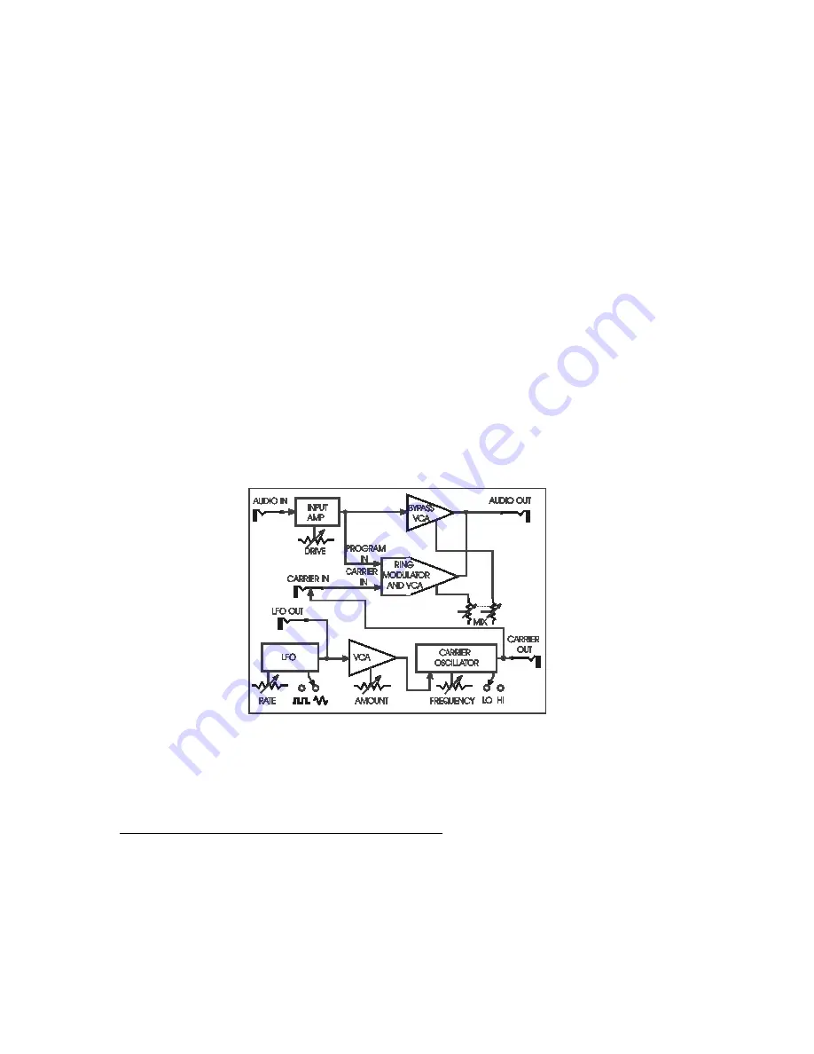
Figure 9 - Block diagram of the MF-102, showing panel controls, switches, and jacks. (Pedal/control jacks are not
shown, but perform the same functions as the control knobs.)

EXPRESSION PEDALS AND VOLTAGE CONTROL

   You now know what each of the rotary control knobs does to the sound of the MF-

102. With the exception of DRIVE, each knob has an expression pedal/control input
which duplicates its effect. This enables you to plug in up to four expression pedals to
play the MF-102 with your feet as well as with your hands. The moogerfooger EP-1
Expression Pedal is designed for this purpose. Or you can use expression pedals with

Содержание Moogerfooger MF-102

Страница 1: ...Understanding and using your moogerfooger MF 102 Ring Modulator...

Страница 2: ...CV converter or any other source of control voltages to play your MF 102 While you can use it on the floor as a conventional effects box your MF 102 is much more versatile and its sound quality is hig...

Страница 3: ...ng modulator is off line bypassed while green indicates that the ring modulator is on line Pressing the stomp switch will toggle the BYPASS light between red and green For now leave the BYPASS light o...

Страница 4: ...instrument s signal is now going through the ring modulator Listen to how the MF 102 affects the quality of your instrument s tone You will hear a distinct vibrato Note that the AMOUNT knob affects t...

Страница 5: ...is a time graph of the actual shape of the vibration while the spectrum shows how strong each of the sound s harmonics is See Figure 3 Figure 3 A musical sound can be represented as a waveform top gra...

Страница 6: ...type of amplitude modulation A ring modulator circuit has two inputs and one output If a sine wave of one frequency is applied to the first input and a sine wave of another frequency is applied to the...

Страница 7: ...the ring modulation of a 500 Hz square wave by a 100 Hz sine wave Figure 7 Waveform and spectrum of a 500 Hz square wave Figure 8 Waveform and spectrum of a 500 Hz square wave ring modulated by a 100...

Страница 8: ...lo Instead your sound will begin to sound rough and detuned because the two sets of harmonics are far enough apart so you begin to hear them as two distinct sounds When the FREQUENCY control is as far...

Страница 9: ...controls to hear the effect of the LFO over its entire range Then set the left switch to square waveform to hear the difference between the two LFO waveforms TOURING THE PANEL FEATURES The LFO Section...

Страница 10: ...al is after being adjusted by the DRIVE control As the signal level increases the light goes from off to green to yellow and finally to red Very weak signals do not light up this light at all When the...

Страница 11: ...CARRIER OUT jacks may be used as control or audio signal sources to control other voltage controlled devices including other moogerfooger analog effects modules The amplitude of the LFO output signal...

Страница 12: ...1 4 tip ring sleeve phone jacks The sleeves are grounded and the ring terminals are supplied with 5 7 volts which is current limited to about 0 5 milliamperes The tip terminals receive the variable vo...

Страница 13: ...ivalent to turning the corresponding knob through its entire range You can program your MF 102 entirely from external control voltages by turning all four control knobs but not the DRIVE knob counterc...

Страница 14: ...roduct to us Wrap your MF 101 carefully and pack it with the power adaptor in its original carton The warranty will not be honored if the product is not properly packed Then send it to Moog Music UPS...

Страница 15: ...FEATURES AUDIO IN 1 4 phone jack accepts any instrument level or line level audio signal from 16 dBm to 4 dbm Input impedance is 1 megohm AUDIO OUT 1 4 phone jack 4 dBm nominal output level Output imp...

Отзывы: