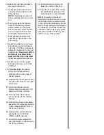
20. Attach the new ball joint inside
the lower control arm.
21. Install new bolts washers and
nuts provided and tighten to 47
ft.lbs. (64 Nm).
NOTE: Install washer onto bolt
before installing bolt into control
arm.
22. Thoroughly clean the tapered
holes of the steering knuckle
before assembly of the studs
with the knuckle. Insert knuckle
over the upper and lower ball
joint studs simultaneously. On
4WD vehicles insert the half
shaft through the spline in the
hub bearing.
23. Install the slotted nut onto lower
ball joint stud nut and torque to
102 ft.lbs. (138 Nm). Continue to
tighten the slotted nut to the next
available slot. Never back off the
slotted nut to achieve align-
ment with the hole in the stud.
Install and spread the cotter pin.
24. Install the nut onto the upper
ball joint and torque to 74 ft.lbs.
(100 Nm)
25. If included install the grease
fitting into the ball joint and
lubricate with a good grade of
chassis grease.
26. Reinstall the wheel speed sensor
harness and bracket to the upper
control arm.
27. Install wheel speed sensor
bracket bolt on control arm and
tighten to 15 ft.lbs. (20 Nm).
28. Reconnect the wheel speed
sensor harness to the chassis
harness.
29. Reinstall the caliper and adapter
assembly to the steering knuckle.
Tighten caliper adapter bolts to
129 ft.lbs. (175 Nm).
30. Reinstall the outer tie rod end
and tighten nut to 33 ft.lbs.
(45Nm) plus 95 degrees.
31. On 4WD vehicles reinstall the
drive shaft axle nut and torque to
191 ft.lbs. (260 Nm).
32. Install the wheel and tire and
lower the vehicle to the floor.
33. Align the front end of the vehicle
to specifications. A check of the
wheel balance is recommended.
NOTE: The parts in this kit are
designed to replace the worn or non-
functioning original equipment parts
in the vehicle as produced by the car
factory. These parts are not designed
for installation on vehicles where the
suspension and/or steering systems
have been modified for racing, com-
petition, or any other purpose


