RP620 Power Vent Indoor Gas Fireplace
Page 36
XG0777 - 100113.1
Installation
4
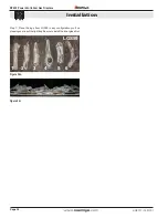
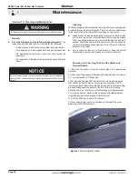
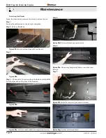
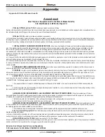
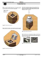
Figure 25i.
Figure 25j.
Ports
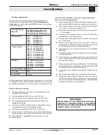
Step 5: Identify logs in kit LSG59
LGS59
1
2
3
4
5 6
Figure 25k.
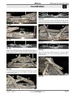
From LGS59, place log 1 on top of log 3 from LGS58 crossing over
the end of the pilot cover. DO NOT place the log on the surface of
the pilot cover, see figure 25l.
Figure 25l.
1
3
From LGS59, place log 4 in front of the ports, infront of the left log
from LGS57. See figure 25m. Place log 6 across the burner tray after
the end of the ports. DO NO place the log over the ports.
Figure 25m.
Figure 25n.
Step 6: From LGS59, place log 3 in front of the ports near the middle
of the burner, in front of the right log from LGS57. Place log 3 on top
of log 3, see figure 25o.
2
3
Figure 25o.
From LGS59, place log 5 in front of the ports near the middle of the
burner, infront of the left from from LGS57. Place log 6 from LGS58
on top of log 5, keeping it in front of the ports, see figure 25q.
Figure 25p.
Figure 25q.
6
5
Optional: You can place a second LGS59 kit in any configuration
pleaseing to you over the light tray. Make sure to install the inner
glass before you do this.


