background image

Installation and repairs should be done by an authorized gas fireplace service technician. 

The appliance should be inspected before use and at least annually by a professional. More 

frequent cleaning may be required due to excessive lint from carpeting, bedding material, 

etc. It is imperative that control compartments, burners and circulating air passageways of 

the fireplace are kept clean.

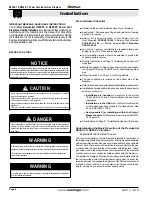
NOTICE

Due to high operating temperatures, this appliance should  be located out of traffic & 

away from furniture and draperies.

Children and adults should be alerted to the hazards of the high surface temperature, 

which could cause burns or clothing ignition.

Young children should be carefully supervised when they are in the same room as the 

appliance.

Clothing or other flammable materials should not be placed on or near the appliance.

CAUTION

When this appliance is installed directly on any combustible material other than wood 

flooring, it must be installed on a metal or wood panel extending the full width and 

depth of the appliance or a fire will occur causing serious injury,  property damage or 

even death.

DANGER

WARNING

A barrier designed to reduce the risk of burns from hot viewing glass is provided with this 

appliance and shall be installed for the protection of children and other at-risk individuals.

If the barrier becomes damaged, the barrier shall be replaced with the manufacturer’s 

barrier for this appliance.

WARNING

Any safety screen, guard, or barrier removed for servicing an appliance must be replaced

prior to operating the appliance.

IMPORTANT MESSAGE: SAVE THESE INSTRUCTIONS

The 

C-View Residential R520-ST & R620-ST Power Vent 

fireplaces must be installed 

in accordance with these Instructions. 

Carefully read all the Instructions in this manual first. Consult the 

Local Gas Branch   to determine the need for a permit prior to starting 

the installation. It is the responsibility of the installer to ensure this 

fireplace is installed in compliance with the manufacturers instructions 

and all applicable codes.

BEFORE YOU START:

Pre-Installation Checklist


■  Determine the desired install location of your fireplace.


■   See Section 1, Dimensions on Page 5, and refer to the Framing 

Section 2 for details. 


■   Select  your  type  and  location  of  your  Power  Vent  run: 

Roof  Mounted 

PVVEX510-300

, External Wall Mounted 

PVHEX510-300

, or 

Flush Louver Wall Mounted 

PVHFL58-300

.


■   Lay out the Vent run; calculating the required elbows and 

straight runs of 5"/10" flex and/or rigid pipe.


■   Your termination location should be selected to provide the 

shortest possible vent run.


■   Refer to the Section 4 on Page 10, "Installing the Power Vent" 

for details.


■   Montigo supplies 20' of low voltage wire, which can be spliced 

to any length. This wire CANNOT run in conduit with any other 

wire.


■   Refer to Section 5 on Page 18, for Wiring Details.


■   The  gas  connection  is  located  on  the  bottom  side  of  the 

fireplace.


■   Refer to local codes and guidelines for installation requirements.


■   Installation and repairs should be done by a qualified contractor 

and must conform to:


•InstallationsinCanada

 must conform to the current 

CAN/CGA B-149.1 and .2 Gas Installation Code and local 

regulations.


•InstallationsintheUSA

 must conform to local codes, 

or in the absence of local codes to the National Fuel Gas 

Code, ANSI Z223.1-1988.


•SeeAppendixCforinstallationwithintheStateof

Massachusetts.

 This fireplace must comply with NFPA-

54 Chapter 10.


■  Refer to Section 6 Page 21, "Installing the Gas Line" for Details.

Understanding the Basic Operation of the Residential 

R520-ST & R620-ST Fireplace

Residential R520-ST & R620-ST fireplace

The control compartment of this fireplace is located in the bottom of 

the fireplace right below the burner system. All models will be supplied 

with a Honeywell smart valve gas control and will not have a variable 

flame control. There are two air switches that are controlling the gas 

control system, and are located in the bottom of this fireplace. These 

gas valves, and  pressure switches communicate with the electrical 

control panel via a six conductor cable supplied with the fireplace. 
To operate the fireplace, Montigo has supplied and installed twenty 

feet of low voltage wire to this electrical control panel. Connect the 

two wire harness to a standard single pole ON/Off switch located at 

a location of your choice. You may also extent these wires to any 

length, as long as you select a wire of equal quality.

R520-ST & R620-ST  Power Vent Indoor Gas Fireplace

Page 4

XG0773 - 150127

Installation

Содержание R520-ST

Страница 1: ...ous to the Environment Danger of harming your hands Irritant Cutting Watch your step Slippery floor High temperatures Glass hazard Danger of suffocation High voltage Toxic Flammable materials Corrosive Fork lift trucks Danger overhead crane Explosion risk Oxidising Danger of death Biohazard Laser Radiation Danger of entrapment Hot surface General Warning Blank Gas bottles Watch for falling objects...

Страница 2: ...g Layout 14 Section 4 2 2 Venting Components 15 Section4 2 3 Installationofthehorizontalexternalwallmountedpower vent module 15 Section 4 3 Heat Shields 15 Section 5 Wiring 16 Installing the Fireplace Control Box 16 Installation of Electrical Supply 17 Installing the Remote Switch 17 Section 6 Installing the gas line 19 Fuel Type 19 Gas Pressure 19 GAS CONNECTION 19 Section 7 Testing the system 20...

Страница 3: ... Montigo disclaims any responsibility for the following actions Modificationofthefireplaceand orcomponentsincluding Power Vent assembly or glass doors Useofanycomponentpartnotmanufacturedorapproved by Montigo in combination with this Montigo fireplace system Installation other than as instructed in this manual Consult your local Gas Inspection Branch on installation requirementsforfactory builtgas...

Страница 4: ...eplace SeeSection1 DimensionsonPage5 andrefertotheFraming Section 2 for details Select your type and location of your Power Vent run Roof Mounted PVVEX510 300 External Wall Mounted PVHEX510 300 or Flush Louver Wall Mounted PVHFL58 300 Lay out the Vent run calculating the required elbows and straight runs of 5 10 flex and or rigid pipe Your termination location should be selected to provide the sho...

Страница 5: ...tallation Basic Operation Thegascontrolcomponentsofthisfireplacearelocatedinthebottom of the firebox below the burner system All models are supplied with a Honeywell smart valve gas control and do NOT have a variable flame control There are two air switches that control the gas control system located in the bottom of the firebox These gas valves and pressure switches communicate with the electrica...

Страница 6: ...73 150127 Installation Rating Plate Sample LBL1207D V5 0 R P VIEW_HSI_WITH SCREEN _DEC 11 2014 Teklynx LabelView Demo Figure A Rating Plate for R520 ST Figure B Rating Plate for R620 ST LBL1207D V5 0 R P VIEW_HSI_WITH SCREEN _DEC 11 2014 Teklynx LabelView Demo ...

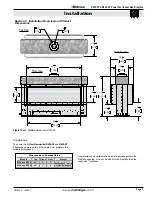
Страница 7: ...safely all models must maintain the following clearances Unprotected combustible walls which are perpendicular to the fireplace opening must not be closer to the fireplace than the required 6 clearance Figure 1 Sec 1 Fireplace dimensions R520 ST 61 1 4 1556 18 1 8 460 59 1 4 1505 16 407 45 1 4 1148 15 1 8 385 13 5 8 346 14 7 8 379 26 1 4 668 23 3 4 605 5 127 10 254 Top View Front View RH Side View...

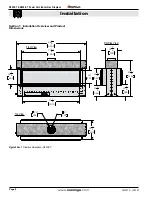
Страница 8: ...eplace dimensions R620 ST 73 1 4 1861 18 1 8 460 71 1 4 1810 16 407 86 3 4 2205 23 3 4 605 5 127 10 254 14 7 8 379 15 1 8 385 13 5 8 346 45 1 4 1148 21 3 4 553 Top View Front View RH Side View R520 ST R620 ST Power Vent Indoor Gas Fireplace Page 8 XG0773 150127 Installation ...

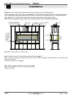
Страница 9: ...top of the platform Please note The top of the platform may not exceed 24 in a room with 8 ceilings Q Opening both sides typical R Opening both sides typical U 3 4 Plywood Platform Max Platform Ht Ceiling Ht 24 8 48 10 R R520 ST 50 23 3 4 R620 ST 78 90 50 23 3 4 Q U Figure 2 Sec 2 Fireplace installation Inlet Gas Power Vent Step 3 Back framing the Fireplace Typical Both sides Back frame in the fir...

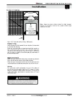
Страница 10: ... 2 Fireplace installation Both Sides are Typical Step 4 Installation of the RHS 102 heat shield See Figure 7 Sec 4 on page 15 When the vent passes through the first adjacent ceiling or wall for horizontal runs a Montigo RHS102 heat shield must be installed around the pipe as shown above See the detail of the RHS 102 on page 13 1 clearance 1 clearance Non Combustible header supplied by Montigo 2 pc...

Страница 11: ...al room temperature and walls above fireplace may be hot to touch Warning We recommend careful consideration be given to the effects of elevated mantel temperatures which may be in excess of product design for example candles plastic or pictures This can cause melting deformation discoloration or premature failure of T V and radio components 12 11 10 9 8 7 6 5 4 3 2 1 Combustible construction allo...

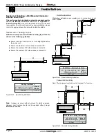
Страница 12: ...ure the maximum vent run does not exceed 80 Ensure the number of 90 elbows does not exceed 6 Ensure the number of 45 elbows does not exceed 12 Figure 3 Typical straight Venting Installations Max V Max Elbows 120 feet N A Multi Elbow Installations Multi elbow installations are possible up to a maximum of six 90 elbows Max V1 H1 V2 H2 V3 Max Elbows 100 feet six 90 Elbow 1 Elbow 2 Elbow 3 Elbow 5 Elb...

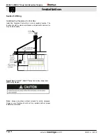
Страница 13: ...te and avoid any possible hot spots Montigo recommends the use of a flex section for the final pipe connected directly to the fireplace offering greater flexibility of installation and absorption of movement All exterior joints in venting should be sealed with high heat silicone RV230 A Termination PVVEX510 300 B Rough in Frame Supplied with PVVEX510 300 C Flex Sections RLF 1 12 Section RLF 2 24 S...

Страница 14: ...ing a Wall Mounted Horizontal Exterior Power Vent Thissectionappliestoinstallationswheretheshortestpossible vent run is through an exterior wall Refer to Appendix A Power Vent locations to ensure the planned Power vent location is acceptable Once the vent location has been established please refer to the appropriate section below for installation details Venting Installation V H Maximum Length Max...

Страница 15: ...ions to ensure the planned Vertical Power vent location is acceptable A Termination PVHEX510 300 Wall Mount 5 10 PVHFL510 300 Flush Wall Mount 5 10 C Flex Sections RFL1 12 f f Section RFL2 24 f f Section RFL3 36 f f Section RFL4 48 f f Section RFL6 72 f f Section D Rigid Sections RXT 10 10 f f Section RXT 20 20 f f Section REXT 1 12 f m Section REXT 2 24 f m Section REXT 3 36 f m Section REXT 4 48...

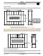
Страница 16: ...ox Power Vent Wire Routing Diagram Installing the Fireplace Control Box Install the Fireplace Control Box in an accessible location The location should be where maintenance adjustments and service may be made easily Control Box Horizontal Power Vent Termination Vertical Power Vent Termination Power cable Installatio n required for either Horizontal or Vertical Termination Vent 115Vac 60 Hz supply ...

Страница 17: ...equal quality InstallationsinCanadamustbeelectricallygroundedinaccordance withCSAC22 1CanadianElectricalCodePart1and orLocalCodes InstallationsintheUSAmustbeelectricallygroundedinaccordance with local codes or in the absence of local codes with the National Electrical Code ANSI NFPA 70 Installation of Electrical Supply The R520ST R620ST is supplied with an external electrical control panel pre wir...

Страница 18: ...s Control SV9501M Gas Control onnector Conduit Wiring clearances 1 Clearance Note If any of the original wire supplied with the appliance is replaced it must be with the same or its equivalent Connect the power vent power cord as outlined in the previous section Ensure that the proper clearances are maintained for the wiring and conduit When installing the wiring it must never run above the vent r...

Страница 19: ...elow for location of gas line access Flexible gas connectors must not exceed 3 feet in length unless allowable within local regulations Connect incoming gas line to the 1 2 Male NPT gas inlet Purge all air out of gas line before connecting port Check appliance connection valve and valve train under normal operatingpressurewithacommerciallyavailableleakchecksolution DO NOT USE A FLAME OF ANY KIND T...

Страница 20: ...e Fireplace This test can be done quickly and efficiently to ensure all systems function according to the design specifications The fireplace should be installed on the rough in frame with the Power Vent Module and the Vent run connected Section 7 Testing the system 7 1 Testing the system before gas connection If the red LED is illuminated beside the fuse you have power to the panel If no LED chec...

Страница 21: ...hot to touch We recommend careful consideration be given to the effects of elevated mantel temperatures which may be in excess of product design for example candles plastic or pictures This can cause melting deformation discoloration or premature failure of T V and radio components Side wall clearances are 6 Combustible surrounds may be installed with6 clearancetothesideofthefireplaceasshowninFigu...

Страница 22: ...way and store in a safe place The Screen is very fragile and canbeeasilytorn dentedordeformed RefertoFigure1Sec 9below Window Screen Assembly Retaining Tabs 2x Ventilation slots located at the bottom of the Screen Assembly Glass Panel Glass Lifting Tools Figure 1 Sec 9Screen Removal Window Screen Assembly Retaining Tabs 2x Ventilation slots located at the bottom of the Screen Assembly Glass Panel ...

Страница 23: ...rating Propane gas fireplace with designer glass Firestones surrounding burner tray Second Gen burner shown Optional River Rocks The R520ST R620ST has the option of installing the cultured rocks which mimic real stone These may be spaced at random or in a visual pattern of your preference See the Montigo web site for photographs and ideas www montigo com Do not operate this fireplace without the g...

Страница 24: ...Start up Sequence TO TURN OFF GAS TO APPLIANCE LIGHTING INSTRUCTIONS FOR YOUR SAFETY READ BEFORE LIGHTING Heat Sensor Conmustion Air R520 ST R620 ST Power Vent Indoor Gas Fireplace Page 24 XG0773 150127 Operation ...

Страница 25: ...e of 10 W C Always keep the fireplace area clear and free of combustible materials as well as gasoline and other flammable vapors and liquids Do not use this appliance if any part has been under water Immediately call a qualified service technician to inspect the appliance and to replace any part of the control system and any gas control which has been under water See Lighting Instructions section...

Страница 26: ...P Gas Valve RGC1003 NG Pilot Assembly RPA003 30 LP Pilot Assembly RPA004 30 Power Vent Control Box RESCB2 Outer Glass RGL1065 RGL1066 Replacement Screen RSCR520 RSCR620 Fuse AGC 5Amp EC1122 R520 ST R620 ST Power Vent Indoor Gas Fireplace Page 26 XG0773 150127 Maintenance ...

Страница 27: ...nthisterminationseeinstructionguide for the PVVEX510 300 PVVEX510 300 Vertical Power Vent Detail Front View Not Acceptable Side View Front View Top View 24 24 Wall Wall 18 40 1016 mm 18 Min Wall 24 610 mm 610 mm 610 mm 457 mm Figure 1 Appendix PVVEX510 300 Figure 2Appendix PVVEX510 300 clearances Figure 3Appendix PVVEX510 300 restrictions ...

Страница 28: ...J Clearance to nonmechanical air supply inlet to building or the combustion air inlet to any other appliance 6in 15 cm for appliances 10 000 Btuh 3 kW 12 in 30 cm for appliances 10 000 Btuh 3 kW and 100 000 Btuh 30 kW 36 in 91 cm for appliances 100 000 Btuh 30 kW Canadian Installations US Installations 1 2 6in 15 cm for appliances 10 000 Btuh 3 kW 9 in 23 cm for appliances 10 000 Btuh 3 kW and 50 ...

Страница 29: ...orinstallationinstructionsonthisterminationseeinstructionguide for the PVHEX510 300 PVHEX510 300 Horizontal Power Vent Detail Eaves Overhang Wal l 14 355mm 32 813mm 16 6 6 Side View 152mm 152mm 406mm Figure 5Appendix PVHEX510 300 Figure 6Appendix PVHEX510 300 Termination Clearances ...

Страница 30: ...lator vent outlet 3 ft 91 cm J Clearance to nonmechanical air supply inlet to building or the combustion air inlet to any other appliance 6in 15 cm for appliances 10 000 Btuh 3 kW 12 in 30 cm for appliances 10 000 Btuh 3 kW and 100 000 Btuh 30 kW 36 in 91 cm for appliances 100 000 Btuh 30 kW Canadian Installations US Installations 1 2 6in 15 cm for appliances 10 000 Btuh 3 kW 9 in 23 cm for applia...

Страница 31: ...HFL510 300 Horizontal Power Vent Detail Front View Eaves Overhang Wall 24 610mm 24 15 15 24 610mm 152mm 152mm 622mm Forinstallationinstructionsonthisterminationseeinstructionguide for the PVHFL510 300 Figure 8Appendix PVHFL510 300 Figure 9Appendix PVHFL510 300 Termination Clearances ...

Страница 32: ...gulator vent outlet 3 ft 91 cm J Clearance to nonmechanical air supply inlet to building or the combustion air inlet to any other appliance 6in 15 cm for appliances 10 000 Btuh 3 kW 12 in 30 cm for appliances 10 000 Btuh 3 kW and 100 000 Btuh 30 kW 36 in 91 cm for appliances 100 000 Btuh 30 kW Canadian Installations US Installations 1 2 6in 15 cm for appliances 10 000 Btuh 3 kW 9 in 23 cm for appl...

Страница 33: ...e designed to burn gas only Burning conventional fireplace fuels such as wood coal or any other solid fuel will cause damage to the Gas Appliance will produce excessive temperatures and will result in a fire hazard Limitations On Liability It is expressly agreed and understood that The Companies sole obligation and purchaser s exclusive remedy under this Warranty under any other warranty expressed...

Страница 34: ...ted gas fueled heating appliance or equipment The sign shall read in print size no less than one half 1 2 inch in size GAS VENT DIRECTLY BELOW KEEP CLEAR OF ALL OBSTRUCTIONS 4 INSPECTION The state or local gas inspector of the side wall horizontally vented gas fueled equipment shall not approve the installation unless upon inspection the inspector observes carbon monoxide detectors and signage ins...

Страница 35: ...R520ST R620ST Power Vent Indoor Gas Fireplace Page 35 XG0773 150127 Notes ...

Страница 36: ...XG0773 150127 R520ST R620ST See Through Gas Fireplace ...

Отзывы: