background image

H36PVN Power Vent Indoor Gas Fireplace

Page 8

XG0649 - 031511

Installation

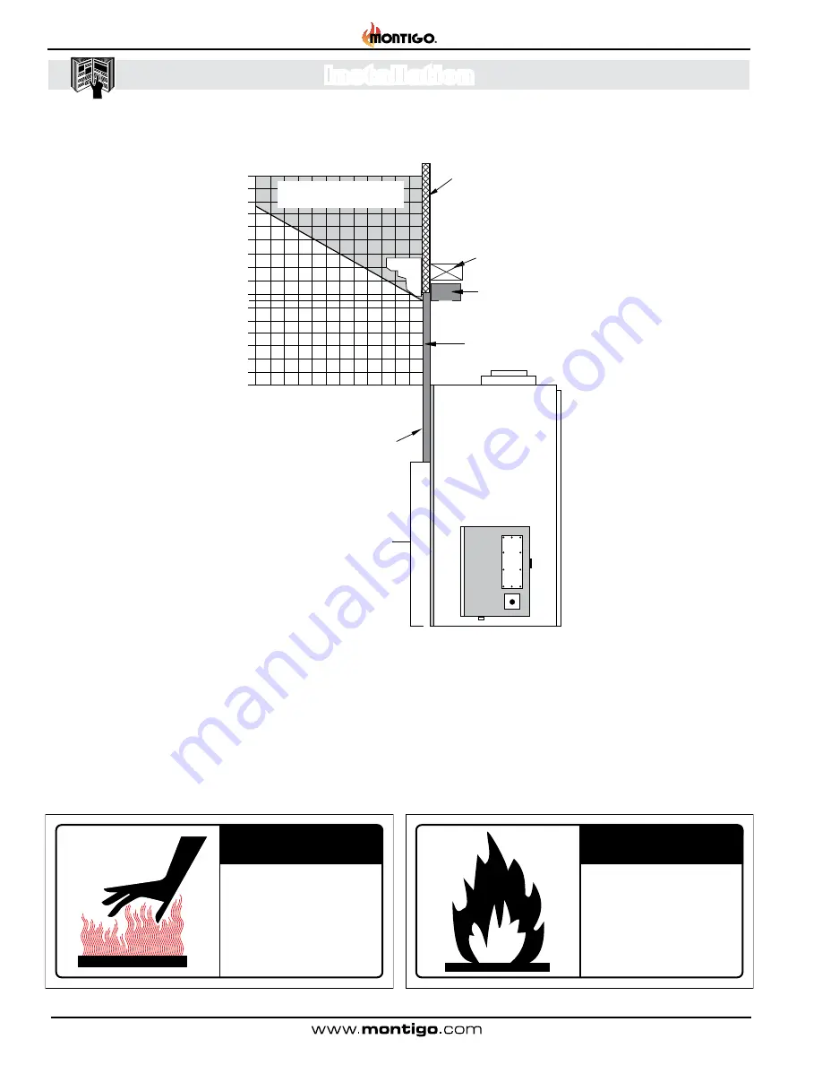
Figure 3b. Combustible mantle and facings. (Not to scale)

Fireplace Facing

When selecting the finish material for your fireplace, it is important 

to remember the following:
If the surround of the fireplace is to be painted to match the room decor, 

heat-resistant paint must be provided  .  Also, decorative facing must 

not extend past the fireplace opening at all, because it will interfere 

with the access to retainers for removal of glass door and access to 

the lower compartment .

Mantels & Surrounds

National Canadian Gas Association mantel test requirements are for 

fire hazard prevention to combustible materials .
Please be aware; temperatures over the mantel will rise above normal 

room temperature and walls above fireplace may be hot to touch .

XW2034

We  recommend  careful  consideration 

be  given  to  the  effects  of  elevated 

mantel temperatures which may be in 

excess of product design, for example: 

candles,  plastic  or  pictures.   This  can 

cause  melting,  deformation,  discolor-

ation or premature failure of T.V. radio, 

and other electronic components.

CAUTION

When  covering  the  upper  metal 

portion of the fireplace, (as shown, 

Fig.16)  with  a  non-combustible 

material,  Please 

Note:

  The 

decorative  facing  materials  may 

be  subject  to  temperatures  in 

excess of 250° F.  This should be 

considered  when  selecting  facing 

materials.

CAUTION

XW2036

Non-Combustible

Cement Board

(supplied by Montigo)

Non-Combustible

Cement Board

(supplied by Montigo)

Drywall/

Combustible Construction

To Ceiling

Horizontal Run

12” 11” 10” 9” 8” 7” 6” 5” 4” 3” 2” 1”

Vertical Run

Glass

16”

15”

14”

13”

12”

11”

10”

9”

8”

7”

6”

5”

4”

3”

2”

1”

Non-combustible

Header (supplied by

Montigo @ 6½”)

Combustible Construction

allowed in shaded area

First Combustible

Header @ 50"

from floor or 8”

from top of unit 

Содержание H36PVN

Страница 1: ... falling objects Electricity Danger for cutter Entrapment hazard Battery hazard Rotating parts Low temperature Strong magnetic field Optical radiation Non ionizing radiation Radiation Hazardous to the Environment Danger of harming your hands Irritant Cutting Watch your step Slippery floor High temperatures Glass hazard Danger of suffocation High voltage Toxic Flammable materials Corrosive Fork lif...

Страница 2: ...talling a Wall Mounted Vertical Exterior Power Vent 13 Venting Layout 13 Multi Elbow Installations 13 Downward Vertical Venting 13 Venting Components 14 Installation of the external wall mounted power vent 15 Installing the external wall mounted power vent module 16 Installing In Line Linear Power Vent 17 Venting Layout 17 Typical Vertical Vent 17 Multi Elbow Vertical Vent 17 Downward Vertical Ven...

Страница 3: ...ding Direct Vent assembly or glass doors Useofanycomponentpartnotmanufacturedorapproved by Montigo in combination with this Montigo fireplace system Installation other than as instructed in this manual Consult your local Gas Inspection Branch on installation requirementsforfactory builtgasfireplaces Installation repairs should be done by a qualified contractor Fireplace BTU H Input Model Natural G...

Страница 4: ...twenty feet of low voltage wire to this electrical control panel Connect the two wire harness to a standard single pole ON Off switch located at a location of your choice You may also extent these wires to any length as long as you select a wire of equal quality XW2018 Due to high operating temperatures this appliance should be located out of traffic away from furniture and draperies Children and ...

Страница 5: ...nd heat should be discussed with the flooring manufacturer If carpet is to laid there must be a 12 clearance or hearth between the front of the fireplace and the start of the carpet The H36PVN H36PVL are power vented fireplace systems Under no circumstances can these model s be installed without a power vent module For regular Horizontal vent installation use 5 8 model EDVWSPV58 with the rough in ...

Страница 6: ...is installed See Figures 1 and 2a Step2 PlacetheFireplaceintheenclosureandinstalltheVentpipe and Power Vent module Next Connect the Gas line and provide a gas service shut off valve according to local gas codes then secure in place with 1 4 wood screws Install supplied Non combustible header at 45 from floor 46 24 50 minimum Flexible incoming gas connection Secure nailing flange to 2 x 4 s using w...

Страница 7: ...al screws Step 2 As shown in figure 3a Cut standard Drywall Wall board to complete the installation of fireplace surround Non combustible Cement Board supplied by montigo Fasten above the glass of the unit to Non combustible header and 2 x 4 s at side of unit Combustible Drywall Wall Board or equivelant Fasten above the glass of the unit to Non combustible header and 2 x 4 s at side of unit Figure...

Страница 8: ...o touch XW2034 We recommend careful consideration be given to the effects of elevated mantel temperatures which may be in excess of product design for example candles plastic or pictures This can cause melting deformation discolor ation or premature failure of T V radio and other electronic components CAUTION When covering the upper metal portion of the fireplace as shown Fig 16 with a non combust...

Страница 9: ...tions where the shortest possible vent runisthroughtheroof RefertoAppendixA PowerVentlocations to ensure the planned Power vent location is acceptable Once the vent location has been established please refer to the appropriate section below for installation details Venting Layout Selectionof componentsanddetails of ventinglayout should adhere to the following guidelines Ensure there is a minimum r...

Страница 10: ... joints in venting should be sealed with high heat silicone 706 High Temp A Termination EDVRSPV58 B Rough in Frame EDVRSPV58F C Flex Sections PLF 1 12 Section PLF 2 24 Section PFL 3 36 Section PFL 4 48 Section D Rigid Sections PEXT 1 12 m f Section PXT 20 20 Section PEXT 2 24 m f Section PEXT 3 36 m f Section PEXT 4 48 m f Section E Elbows PEL 90MM m m 90º Elbow PEL 90FF f f 90º Elbow PEL 90FM f m...

Страница 11: ...er of the rough in box and snap into the slot provided See figure 5b inset Figure 5c Fasten Rough in Kit to framing Step 4 InstallfastenersaroundperimeterofRough inKit Holessupplied for ease of installation Figure 5d Installed Stainless steel cover Installing the external roof mounted power vent module All venting material must be sealed with high heat silicone sealant RV230 All venting material t...

Страница 12: ...inal position Ensure the Harness is placed down in the Rough in box when placing the Power Vent Module into place The Power Vent Module will sit flush with the stainless steel cover if installed correctly Figure 5h Installed Power Vent Module Step 8 Install 3 three stainless steel fasteners around Power Vent Module 120 degrees penetrating through the inner stainless steel vent cover Stainless Stee...

Страница 13: ...possible vent run is through an exterior wall Refer to Appendix A Power Vent locations to ensure the planned Power vent location is acceptable Once the vent location has been established please refer to the appropriate section below for installation details Once the vent location has been established please refer to the appropriate section below for installation details All venting material must b...

Страница 14: ...igh heat silicone RV230 Installation of the EDVWSPV58 external wall mounted power vent module Refer to Appendix A Power Vent locations to ensure the planned Vertical Power vent location is acceptable The EDVWSPV58 Power Vent dimensions The EPVF58 Rough in Frame dimensions 9 3 4 10 9 16 5 9 0 11 1 16 11 1 16 11 1 16 10 9 16 5 9 0 14 1 4 14 1 16 1 1 2 4 9 16 8 12 1 8 9 11 16 12 5 16 4 9 11 16 ISOMET...

Страница 15: ...quirements Opening Size must be 14 1 2 x 14 1 2 Figure 7c Installation of Power Vent Conduit Power Vent Conduit Strain Relief Nut Step 4 Insert the conduit from the Power Vent Module into the rough in frame through the two top right entry holes Remove the nut from the supplied strain relief and place as shown Figure 7c Strain Relief Figure 7d Installing Conduit connector conduit mounting frame Pow...

Страница 16: ... buildup from obstructing the vent termination CAUTION XW2026 Step 8 Install the Power Vent Power communication harness Hold the Power Vent in close proximity of the assembled Rough in Kit and plug in the Power Vent communication Power Cord Note the direction and orientation of the pins inside the Power Vent connector snap together Figure 7f Step 9 Install the Power Vent Place the Power Vent into ...

Страница 17: ...n feet 10 0 for every additional 90 elbow added Also deduct ten feet 10 0 of vent length for every one foot 1 0 of vent run traveling in a downward direction Figure 7b HorizontaI Linear Power Vent with Downward vent and Horizontal Vent Run to Termination CAUTION Vent terminations can be very hot The termination is to be installed higher than 7 feet above a public walkway Do not obstruct or attempt...

Страница 18: ...arateandavoid any possible hot spots Montigo recommends the use of a flex section for the final pipe connected directly to the fireplace offering greater flexibility of installation and absorption of movement All exterior joints in venting should be sealed with high heat silicone RV230 A Termination DVPV58 C Control Module D Flex Sections G Power Cord Harnesses F Elbows B Power Vent LDVPV58 RHSIT0...

Страница 19: ...an and flush so it does not interfere or have an impact with your architectural design NOTE TheH36PVNrequiresaspecificvolumeofatmosphericinterchange to operate properly and efficiently ThefireplacerequiresaMIN80in sq airmovementtofunction The grille must also be able to shed water not allowing any moisture to enter the unit Recessed Termination Installation VLWB 8 Refer to Appendix A Termination l...

Страница 20: ...e the exterior Access cover shown Figure 12a Step 2 LocateallthePowerventconnections ports Figure12b Figure 12b Locate Power vent connections Note To access the fireplace electrical connections from the fireboxfollowtheproceduresdescribedinfigure22through26 Power Vent A C Access Cover Power Vent Communica tion port Power vent communi cation conduit A C connection port Incoming A C Power Connection...

Страница 21: ...e 12d Note orientation of conduit plug into the Port flat side notches Figure 12e Installing Conduit Port Cover Plate Note orientation of connector Power vent communication harness port Power vent communication harness Power vent communication port cover Power vent communication port cover strain relief Power vent communication port cover fasteners Installing The Remote Switch TheH36PVN sRemoteLVT...

Страница 22: ...e Page 22 XG0649 031511 Installation Figure 13 Wiring schematic for the H36PVN If the information in these instructions is not followed exactly a fire or explosion may result causing property damage personal injury or death WARNING XW2008 ...

Страница 23: ...power vent as outlined in the previ ous section and connect the wiring to the fireplace as outlined in the H36PVN schematic figure 13 Ensure that the proper clearances are maintained for the wiring and conduit When installing the wiring it must never run above the vent run and it must be at least 1 clear of all venting 1 Clearance Figure 13a H36PVN SIT IPI Wiring Schemmatic ...

Страница 24: ...atible contact your local Montigo representative to purchase a conversion kit Conversion kits must be installed by a qualified service technician GAS PRESSURE Optimum appliance performance requires proper input pressures Gas line sizing requirements will be determined in ANSI Z221 3 National Fuel Gas Code in the USA and CAN CGA B149 in Canada Pressure requirements are The manifold outlet pressure ...

Страница 25: ...top edge of the door frame into place Lower and rest the door frame in place and fasten the buckles See figures 28a and 28b Installing the Door Figure 17c Lift the door upward Figure 17d Lift the bottom of the door outward Figure 17e Step 3 Hold the Glass Removal Tools firmly Lift the door upward into the top door frame Figure 17c Then pull the bottom of the glass doordownward andtiltoutwardfromth...

Страница 26: ...etal Back Pan Without pressing the Log down move it as far to the left as possible bumping the bottom Left corner against the alignment tab Figure 18a 18d Lastly Press the Log FIRMLY downward onto the sharp spikes shown in Figure 18a 18e Step 4 Once the Back Log A is in it s final Position hold the log in place and reinstall the Retaining Clip removed earlier Press down the Clip for the sharp teet...

Страница 27: ...spikes Figure 18i Note the color variation in the Log Figure 18i Installation of Log C Step 7 Place Bottom Left Log D with the flat edge down and place square end inside Log Rest aligning the center of the Log with the Spikes Figure 18a Press FIRMLY seating the Log onto the sharp spikes Figure 18j Note the color variation in the Log Step 8 Place Front Left Log E with the Knots pointing in the dire...

Страница 28: ...and then ON again will reset this start up sequence 6 Once the pilots are burning the main burner will turn on and the fireplace will be functional for a quick start up on next use If the information in these instructions is not followed exactly a fire or explosion may result causing property damage personal injury or death WARNING XW2008 This fireplace has been set up at the factory for a determi...

Страница 29: ...l next to the floor because some gas is heavier than air and will settle on the floor What To Do If You Smell Gas Do not try to light any appliance Do not touch any electrical switch do not use any phone in your building 1 STOP Read the safety information above on this label 2 Remove the lower Horizontal access panel 3 Turn Incoming gas valve to the ON position 4 Wait 5 minutes to clear out any ga...

Страница 30: ...may damage the flexible gas hose or mounting hardware of the grate Figure 14e Figure 20d Loosening Gas fitting on burner Removing the Refractory The H36PVN is supplied three 3 pieces of firebox refractory Lining These panels are fastened directly to the interior sides and back of the Fireplace firebox with brackets To remove the brackets and panels follow the steps described below Step 1 Remove th...

Страница 31: ...l Figure 24 24a Philips head screwdriver required Figure 24a Removing interior stand off panels Side panel retaining bracket 4 places Grate Removing the Access Panel The H36PVN is supplied one 1 one interior access Panel RH side that contains the electronics and power control circuits This panel is fastened directly to the interior of the firebox with sheet metal screws To remove the panel follow ...

Страница 32: ... connection Ensure proper log placement as per this manual Inspection of all optional equipment fans thermostats etc ForNaturalGasthisappliancerequiresaminimuminletpressure of 5 5 W C and a manifold pressure of 3 5 W C ForPropaneGasthisappliancerequiresaminimuminletpressure of 11 W C and a manifold pressure of 10 W C Always keep the fireplace area clear and free of combustible materials as well as...

Страница 33: ...053 Pilot Tubing 18 Length RPTA03 Control Module RGC3035 Wiring Harness RGC3041 DC Adapter RGC3043 Power Vent Control Box ECB007 Log Set RLGSHW42 1 Locate the lead to the battery backup remove Refer to schematic below 2 Locate the AC DC wall transformer Unplug connector Refer to schematic below Troubleshooting SIT IPI Electronic 1 2 If your fireplace still does not operate correctly consult your d...

Страница 34: ... minimum in Canada L clearancetonon mechanicalairsupplyinlettobuildingorthecombustion airinlettoanyotherappliance 16inches 41cm minimumforappliances 100 000 BTU H 30kW M clearance to mechanical air supply inlet 6 feet 1 8 m minimum N clearanceabovepavedsidewalkorapaveddrivewaylocatedonpublic property 7 feet 2 1 m minimum P clearance under veranda porch deck or balcony 30 inches 75 cm minimum to no...

Страница 35: ...A Power Vent Locations Front View EDVRSPV58 Vertical Power Vent Detail EDVWSPV58 Horizontal Power Vent Detail Top View Front View Front View 30 Min 30 Min Eaves Overhang Wall F G H I 30 75cm Min V 18 24 61cm Min V 18 Min Wa ll R 30 Min R 30 Min R Wall Wall Side View Not Acceptable ...

Страница 36: ...he Companies 2 The Montigo Gas Appliance must be subjected to normal use The Gas Appliances are designed to burn gas only Burning conventional fireplace fuels such as wood coal or any other solid fuel will cause damage to the Gas Appliance will produce excessive temperatures and will result in a fire hazard Limitations On Liability It is expressly agreed and understood that The Companies sole obli...

Страница 37: ... height of eight 8 feet above grade directly in line with the exhaust vent terminal for the horizontally vented gas fueled heating appliance or equipment The sign shall read in print size no less than one half 1 2 inch in size GAS VENT DIRECTLY BELOW KEEP CLEAR OF ALL OBSTRUCTIONS 4 INSPECTION The state or local gas inspector of the side wall horizontally vented gas fueled equipment shall not appr...

Страница 38: ...H36PVN Power Vent Indoor Gas Fireplace Page 38 XG0649 031511 Notes ...

Страница 39: ...H36PVN Power Vent Indoor Gas Fireplace Page 39 XG0649 031511 Notes ...

Страница 40: ...Ferndale Washington TF 1 800 789 6236 FX 1 866 3000 0927 XG0649 031511 Langley British Columbia TF 1 800 378 3115 FX 1 604 607 6462 H36 PV Power Vented Residential Gas Fireplace ...

Отзывы: